This thread has been locked.

If you have a related question, please click the "Ask a related question" button in the top right corner. The newly created question will be automatically linked to this question.

TMS320F280049C: PGA Ramp Response

Part Number: TMS320F280049C

In the F280049C, there is a maximum step response settling time listed for the PGA's.  However, really looking to quantify from a ramp response perspective.  For example, if there is signal that ramps from DC to X Volts/mSec into the PGA input, what is the ramp response at the PGA output (independent of filters)? 

Another way to look at this is to characterize as a second order system.  If so, then could parameterize in MATLAB and simulate expected ramp response.   This does start to get a little complicated from a PVT perspective...  So not sure what the best approach is.  Looking for some guidance to understand ramp settling time and steady state error.   

  • Hi Eric,

    Interesting question. I don't think any op-amps have this parameter. Nevertheless for the PGAs, there is a lower bound in the datasheet where we specify the min ADC S/H required at each of the gain settings.

    However you should be able to quantify this to some degree but i need to understand what you are looking to achieve from the ramp. Are you looking to sample the ramp at intermediate points or when it's at it's final value?

  • Hi Frank,

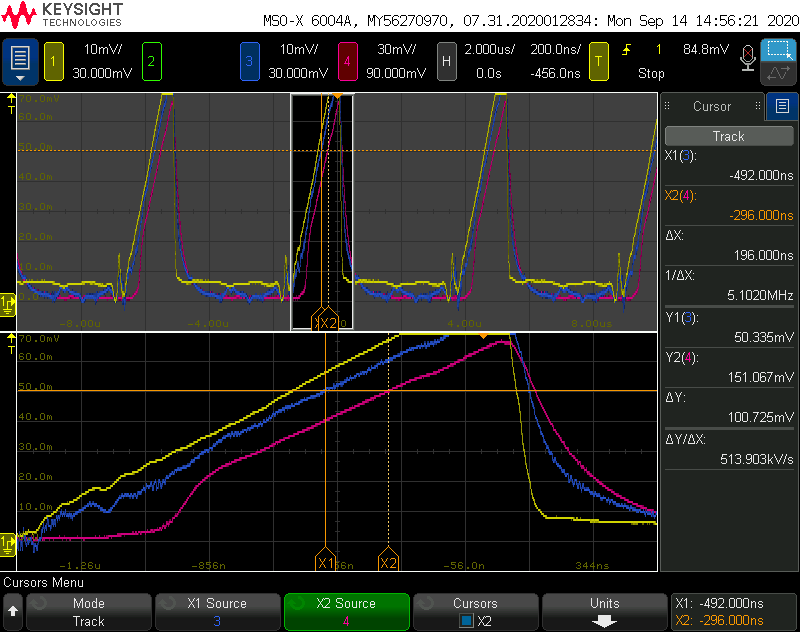
    The best way to think about this is from an accuracy perspective.  For example, would like to understand the delta between the actual signal being sensed vs the output of the PGA to the CMPSS.  A typical system may have a filter, and the associated group delay (and of course other contributions of propagation delays).  The contributions of filters can be calculated in a straight forward manner.  In this particular case, the focus is on the PGA itself (input to output) of a ramp input.  Looking for a method to estimate the PGA output response lag to a ramp input.  From an empirical data point with a reasonably fast ramp, this response lag can be in the order of 200nSec (measured directly from input to output).  The goal is to better understand the PGA response to a ramp with the potential to compensate properly for improved accuracy.

    At the onset of the ramp, I assume the error could be worse.  So trying to understand the error at the end of the ramp.  Please see the scope plot below.  Yellow is actual signal measured at sense resistor.  Blue is input to PGA (some filtering prior to input, and group delay approx. 100nS).  Red is output from PGA (with approx. 200nS lag).  The group delay from yellow to blue is fully understood.  Would like to understand how to quantify the deltas from blue to red, PGA in to out.

    -Eric

    cid:image002.png@01D68AA8.65CF6DC0

  • Please note, this is a false alarm.  There was a measurement error involved here with the red trace (miscalculation of the filter network contribution and some extra gain error due to some impedance).  Apologize for the false start.  This can be closed out.

  • Hi Eric,

    I was just about to reply. Glad to hear the issue is resolved. Let us know if anymore crop up.