This thread has been locked.

If you have a related question, please click the "Ask a related question" button in the top right corner. The newly created question will be automatically linked to this question.

CCS/TMS320F28386D: How to trigger CM Watchdog reset?

Part Number: TMS320F28386D
Other Parts Discussed in Thread: C2000WARE

Tool/software: Code Composer Studio

Hello,

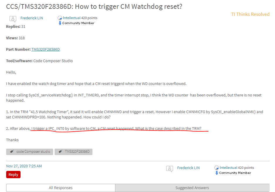
I have enabled the watch dog timer and hope that a CM reset triggerd when the WD counter is overflowed.

I stop calling SysCtl_serviceWatchdog() in INT_TIMER0, and the timer interrupt stop, I think the WD counter  has been overflowed, but there is no reset happened.

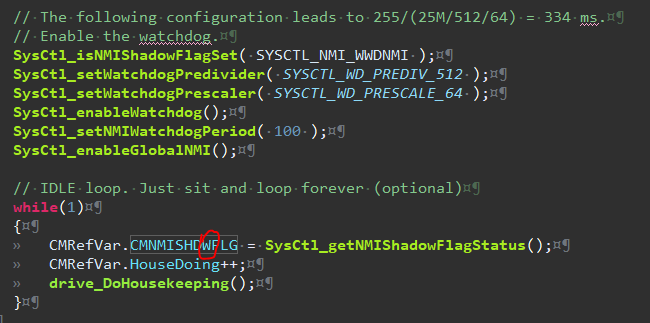
1. In the TRM "41.5 Watchdog Timer", it said it will enable CMNMIWD and trigger a reset. However I enable CMNMICFG by SysCtl_enableGlobalNMI() and set CMNMIWDPRD=100. Nothing happended. How could I do?

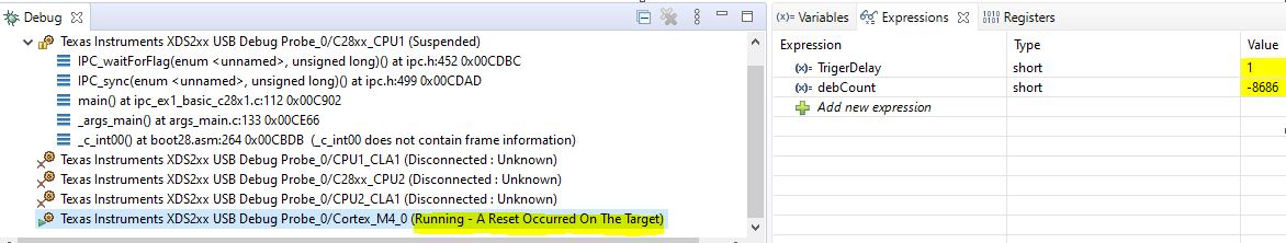
2. After above, I trigger a IPC_INT0 by software to CM, a CM reset happened. What is the case described in the TRM?

Thanks

  • Hi,

    The subject matter expert assigned to this thread is out of office this week due to the the US holiday so you may not get a qualified answer until next week. I apologize for the delay.

    Regards,

    Himanshu

  • Hi Fredrick,

    Can you check if WWDNMI flag is set in CMNMISHDWFLG register. If not then for some reason WD overflow is not happening and you need to check the correct configuration of Watchdog like if WD is enabled as expected (check the value in CCS register view after running the code).

    Regards,

    Vivek Singh

  • Hi Vivek,

    I read CMNMISHDWFLG  by SysCtl_getNMIShadowFlagStatus() and it return zero.

    Below is my code about CM watch dog configuration. Can you help me find out what's wrong with it?

    And it's NMI register status:

    Regards,

    Frederick

  • Frederick,

    Do you have NMI handler in your code ? After NMI, CPU will jump to NMI handler hence code reading  NMI shadow flag may not get executed. If you have NMI handler, put a breakpoint at entry of NMI handler and see if CPU jumps there.  

    Also did you check the below -

     you need to check the correct configuration of Watchdog like if WD is enabled as expected (check the value in CCS register view after running the code).

    Regards,

    Vivek Singh

  • Vivek,

    " you need to check the correct configuration of Watchdog like if WD is enabled as expected (check the value in CCS register view after running the code)."

    I check the CCS register during normal running, The values look correct as expected.

    "Do you have NMI handler in your code ? After NMI, CPU will jump to NMI handler hence code reading  NMI shadow flag may not get executed. If you have NMI handler, put a breakpoint at entry of NMI handler and see if CPU jumps there.  "

    I created a FAULT_NMI interrupt. The CPU jump into as expected. In the interript function, I latched SysCtl_getWatchdogStatus() returned true, SysCtl_getNMIFlagStatus() returned NMIINT and WWDNMI. They are as expected.

    However, if I do not call SysCtl_clearWatchdogStatus() and SysCtl_clearAllNMIFlags(), I expected it should generate a reset and restart the main() function, but as below:

    1. Link XDS110 debuger into my code: It jump into NMI interrupt and generated a reset and restart the main() function as expected.

    2. Standalone mode( cm boot by cpu1, and not link XDS110): It jump to into NMI interrupt with correct WatchdogStatus and NMIFlags, but just hold on the situation. No reset generated.

    What difference between the two mode? If I want a reset generated in Standalone, how can I do?

    Regards,

    Frederick

  • Frederick,

    If I understand correctly, now you see it generating the reset as expected when XDA110 is connected. Right ?

    But when you are running standalone, you do not see reset getting generated ? Right?

    If both are correct then in standalone mode, how are you confirming that reset is not happening ? 

    Regards,

    Vivek Singh

  • Vivek ,

    Yes, your understanding is correct.

    " how are you confirming that reset is not happening ? "

    I have some debug code in CMtoCPU1Ram, our UI interface can monitor them. Their initial values are zeros.

    After NNI interrupt, their value hold on and not restore to zeros.

    But with XDS110, all of them to zeros.

    Regards,

    Frederick

     how are you confirming that reset is not happening ? 

  • Frederick,

    Ok thanks. But in case of standalone, after reset CM will boot again and variable will get initialize and the time delay is very short so it may be difficult to observe any change unless you have some trigger mechanism which capture the value on change. Would it be possible to use some GPIO pin and monitor the toggle on that based on CM reset ?

    Regards,

    Vivek Singh

  • Vivek,

    I set a GPIO master as CM and it is for trigger led light. I toggle the GPIO at the start of main() after CM_init().

    After the NMI happened, the GPIO status have no changed.

    Also, I set a variable for counter in my main IDLE loop. After the NMI happened, the counter is just stop. Not return to the initial value 0 as expected. I think there is no reset happened.

    However with same code, all the above are expected with JTAG XDS110.

    gpio toggle code:

    WDT setting and main IDLE loop counter:

    Regards,

    Frederick

  • Frederick,

    Is it possible to send me the sample project which you are using so that I can try to run this on my setup here ?

    Regards,

    Vivek Singh

  • Vivek,

    I can only provide my cm sample project because the cpu project is too complicated. sorry.

    cmProject_forTi.zip

    In the CPU1, there are only below codes to boot cm in the standalone mode. Nothing else is related to CM's configuration.

    Regards,

    Frederick

  • Ok thanks. Let me see if I can run this on my setup here and reproduce the issue. 

    Regards,

    Vivek Singh

  • Frederick,

    I checked your code. It has timer interrupt ISR which was servicing WD so I wondering how were you even getting WD NMI from this code -

    // CpuTimer0ISR - Counter for CpuTimer0
    __interrupt void CpuTimer0ISR(void)
    {
    // Reset watchdog timer
    SysCtl_serviceWatchdog();
    }

    After I commented out this line of code then I was able to get NMI and also the reset from NMI. Let me know if you were using same code.

    Regards,

    Vivek Singh

  • Vivek ,

    I used a debug flag to stop servicing the watch dog.

    As below, I set "debug" flag =1 to trigger NMI.

    // CpuTimer0ISR - Counter for CpuTimer0
    __interrupt void CpuTimer0ISR(void)
    {
    // Reset watchdog timer

    if( debug == 0 )
         SysCtl_serviceWatchdog();
    }

    Can you try it in standalone mode?

    Regards,

    Frederick

  • Hi Frederick,

     Can you try it in standalone mode?

    There is no difference with CCS connected and standalone for this. We have a NMI flash for CM NMI watchdog on CPU1 (in NMIWDFLG register). You can configure CMTOCPU1NMICTL register to generate NMI on CPU1 if CM NMIWD triggers a reset to CM and then you can check the status of same when CM is running standalone but CPU1 is connected to debugger.

    Regards,

    Vivek Singh

  • Hi Vivek ,

    " CM is running standalone but CPU1 is connected to debugger."

    I meet a problem in the configuration and I can't continuous doing your suggested test steps.

    After jtag connect to CPU1(only), I reset and restart cpu1.

    After CPU1 boot CM by standalone, the counters in cputimer1 and idle loop are not counter(hold on zero).

    In the begining of cm main(), I called SysCtl_getResetCause and get CMRSTCTL_RESETREQ, CPU1_SYSRSN, XRSn(CPU Get from debug variable in CmToCpuMsgRam).

    However all of cpus and CM are in standalone, the CM counters count as normal.

    What happend to this phenomenon?

    Regards,

    Frederick

  • Frederick,

    I am not sure why behavior of CM standalone will be different between CPU1 running with JTAG connected vs standalone. Only difference is that when you connect CPU1, Gel file will release reset to CM so in your CPU1 application code where you release reset to CM, you can try Ist resetting CM (since it is out of reset) and then release CM reset to start fresh.

    Regards,

    Vivek Singh

  • Frederick,

    I hope your issue got resolved?

    Regards,

    Vivek Singh

  • Vivek,

    Sorry for the delay.

    I find why the behaviors difference between standalone and Jtag.

    When I use JTAG, I still called "Device_bootCM( BOOTMODE_BOOT_TO_FLASH_SECTOR0 );" But cm has been boot by the JTAG.

    It cause remain IPCFLAG0 and trigger a ipc0 interrupt to CM after CM watchdog time out.

    If I clear the IPCFLAG0, the behaviors are same between standalone and Jtag.

    So,I have the below question now.

    1. After cm watchdog timeout and NmI interrupt, there is no reset happended and just hold on.

    2. On the above hold on situation, why a CM IPCFLAG0 interrupt triggered can make it reset? 

    Thanks

  • When the hold on situation, I click pause and it show a strange address

  • That message is just saying that for current PC CCS is not able to find the symbol info. It happens when CPU halts at location which is not a compiled code or pointing to BOOTROM code.

    Regards,

    Vivek Singh

  • Hi Vivek ,

    My problem has not be solved.

    I can reproduce the problem by modify the example "C:\ti\c2000\C2000Ware_3_02_00_00\driverlib\f2838x\examples\c28x_cm\ipc\ipc_ex1_basic_cm".

    It is my modified .c file.

    Set "TrigerDelay" to 1 in the debugger Expressions, and the problem will be reproduced.

    ipc_ex1_basic_cm.c
    //#############################################################################
    //
    // FILE:   ipc_ex1_basic_cm.c
    //
    // TITLE:  IPC example with interrupt
    //
    //! \addtogroup driver_cm_c28x_dual_example_list
    //! <h1> IPC basic message passing example with interrupt </h1>
    //!
    //! This example demonstrates how to configure IPC and pass information from
    //! C28x to CM core without message queues
    //! It is recommended to run the C28x1 core first, followed by the CM core.
    //!
    //! \b External \b Connections \n
    //!  - None.
    //!
    //! \b Watch \b Variables \n
    //!  - None.
    //!
    //
    //#############################################################################
    // $TI Release: F2838x Support Library v3.02.00.00 $
    // $Release Date: Tue May 26 17:21:56 IST 2020 $
    // $Copyright:
    // Copyright (C) 2020 Texas Instruments Incorporated - http://www.ti.com/
    //
    // Redistribution and use in source and binary forms, with or without 
    // modification, are permitted provided that the following conditions 
    // are met:
    // 
    //   Redistributions of source code must retain the above copyright 
    //   notice, this list of conditions and the following disclaimer.
    // 
    //   Redistributions in binary form must reproduce the above copyright
    //   notice, this list of conditions and the following disclaimer in the 
    //   documentation and/or other materials provided with the   
    //   distribution.
    // 
    //   Neither the name of Texas Instruments Incorporated nor the names of
    //   its contributors may be used to endorse or promote products derived
    //   from this software without specific prior written permission.
    // 
    // THIS SOFTWARE IS PROVIDED BY THE COPYRIGHT HOLDERS AND CONTRIBUTORS 
    // "AS IS" AND ANY EXPRESS OR IMPLIED WARRANTIES, INCLUDING, BUT NOT 
    // LIMITED TO, THE IMPLIED WARRANTIES OF MERCHANTABILITY AND FITNESS FOR
    // A PARTICULAR PURPOSE ARE DISCLAIMED. IN NO EVENT SHALL THE COPYRIGHT 
    // OWNER OR CONTRIBUTORS BE LIABLE FOR ANY DIRECT, INDIRECT, INCIDENTAL, 
    // SPECIAL, EXEMPLARY, OR CONSEQUENTIAL DAMAGES (INCLUDING, BUT NOT 
    // LIMITED TO, PROCUREMENT OF SUBSTITUTE GOODS OR SERVICES; LOSS OF USE,
    // DATA, OR PROFITS; OR BUSINESS INTERRUPTION) HOWEVER CAUSED AND ON ANY
    // THEORY OF LIABILITY, WHETHER IN CONTRACT, STRICT LIABILITY, OR TORT 
    // (INCLUDING NEGLIGENCE OR OTHERWISE) ARISING IN ANY WAY OUT OF THE USE 
    // OF THIS SOFTWARE, EVEN IF ADVISED OF THE POSSIBILITY OF SUCH DAMAGE.
    // $
    //###########################################################################
    
    //
    // Included Files
    //
    #include "cm.h"
    #include "ipc.h"
    
    //
    // Defines
    //
    #define IPC_CMD_READ_MEM   0x1001
    #define IPC_CMD_RESP       0x2001
    
    #define TEST_PASS          0x5555
    #define TEST_FAIL          0xAAAA
    __interrupt void cmnmiISR(void);
    
    
    //
    // IPC ISR for Flag 0.
    // C28x core sends data without message queue using Flag 0
    //
    void IPC_ISR0()
    {
        int i;
        uint32_t command, addr, data;
        bool status = false;
    
        //
        // Read the command
        //
        IPC_readCommand(IPC_CM_L_CPU1_R, IPC_FLAG0, IPC_ADDR_CORRECTION_ENABLE,
                        &command, &addr, &data);
    
        if(command == IPC_CMD_READ_MEM)
        {
            status = true;
    
            //
            // Read and compare data
            //
            for(i=0; i<data; i++)
            {
                if(*((uint32_t *)addr + i) != i)
                    status = false;
            }
        }
    
        //
        // Send response to C28x core
        //
        if(status)
        {
            IPC_sendResponse(IPC_CM_L_CPU1_R, TEST_PASS);
        }
        else
        {
            IPC_sendResponse(IPC_CM_L_CPU1_R, TEST_FAIL);
        }
    
        //
        // Acknowledge the flag
        //
        IPC_ackFlagRtoL(IPC_CM_L_CPU1_R, IPC_FLAG0);
    }
    
    //
    // Main
    //
    short TrigerDelay = 0;
    short debCount = 0;
    void main(void)
    {
    
        //
        // Initialize device clock and peripherals
        //
        CM_init();
    
    //    //
    //    // Clear any IPC flags if set already
    //    //
    //    IPC_clearFlagLtoR(IPC_CM_L_CPU1_R, IPC_FLAG_ALL);
    //
    //    //
    //    // Enable IPC interrupts
    //    //
    //    IPC_registerInterrupt(IPC_CM_L_CPU1_R, IPC_INT0, IPC_ISR0);
    //
    //    //
    //    // Synchronize both the cores.
    //    //
    //    IPC_sync(IPC_CM_L_CPU1_R, IPC_FLAG31);
    
        // The following configuration leads to 255/(25M/512/64) = 334 ms.
        // Enable the watchdog.
        Interrupt_registerHandler(FAULT_NMI,cmnmiISR);
        Interrupt_enable(FAULT_NMI);
        SysCtl_clearAllNMIFlags();
        SysCtl_setWatchdogPredivider( SYSCTL_WD_PREDIV_512 );
        SysCtl_setWatchdogPrescaler( SYSCTL_WD_PRESCALE_64 );
        SysCtl_enableWatchdog();
        SysCtl_setNMIWatchdogPeriod( 100 );
        SysCtl_enableGlobalNMI();
    
        //
        // Loop forever. Wait for IPC interrupt
        //
        while( 1 ) {
            // Reset watchdog timer
            if( !TrigerDelay ) {
    
                SysCtl_serviceWatchdog();
            }
    
            debCount++;
        }
    
    }
    
    short Wdstatus = 0;
    short NMIFlagStatus = 0;
    __interrupt void cmnmiISR(void)
    {
       // Get the WWD status and clear it
       Wdstatus = SysCtl_getWatchdogStatus();
    //  SysCtl_clearWatchdogStatus();
    
       // NMI was handled after the WWD expired
       NMIFlagStatus = SysCtl_getNMIFlagStatus();
    //  SysCtl_clearAllNMIFlags();
    
    }
    
    //
    // End of File
    //
    

    Regards,

    Frederick

  • Hi Fredrick,

    Please provide the exact steps to follow to reproduce the issue and also the failure signature or what to observe to make sure I see same failure.

    Regards,

    Vivek Singh 

  • Hi Vivek ,

    In ccs v9.3.0.00012 

    1. Link XDS110 debug probe.

    2. Connect CM core and burn in program.

    3. Click reset and restart buttons.

    4. When it is nunning, Add debCount and TrigerDelay to watch expressions window.

    5. You will see the "debCount " is counting.

    6. Set TrigerDelay =1 in watch expressions window to make it wdt timeout.

    7. I expect debCount return to zero after cm reset, but it just stop. It seem no reset happened.

    Above are my reproduce step.

    Thanks

  • Thanks. I'll check this and get back to you early next week. Are you loading any code on CPU1 for this ?

    Regards,

    Vivek Singh

  • Hi Vivek ,

    Yes, there is my previous program in CPU1.

    I don't know how to just erase program without programing by debugger tool.

    Regards,

    Frederick

  • You can open the flash plug-in GUI and then select the flash sector you want to erase and then click on erase.

    Regards,

    Vivek Singh

  • Hi Frederick,

    I tried this and don't see any issue. When I change the TrigerDelay value to '1'. I see a reset happening on CM core. Please see snapshot below.

    Please note variable don't get to zero just by reset. You have re-run the code after reset and then only variable get initialize.

    Hope this helps and we can close this post.

    Regards,

    Vivek Singh

  • Hi Vivek,

    My debug view show that was still running after set TrigerDelay =1.

    But I can see CMSYSCTL.CMRESC.CMNMIWDRSTn change from 0 to 1, so it reset as expect. This is no problem.

    "You have re-run the code after reset and then only variable get initialize."

    Can I trigger re-run by software in CM self? Or Does it must be call re-run by CPU1?

    Our requirement is that re-run the CM after WDRS happended. After re-run, check CMNMIWDRSTn bit in CMSYSCTL.CMRESC to our own status monitor.

    Regards,

    Frederick

  • Hi,

     Can I trigger re-run by software in CM self? Or Does it must be call re-run by CPU1?

    CPU1 need to provide proper IPC boot command for CM to boot. Please refer "CM Boot Flow" figure in TRM for the detail.

    Regards,

    Vivek Singh 

  • Hi Vivek ,

    To my previous phenomenon description(below 2.).

    If I trigger CPU1 to CM interrupt 0 after CM reset, the CM will restart.

    Is it just match the "Wait for CPU1 to set IPCFLG0" flow in the boot flow, so it restart?

    Thank you.

  • Frederick,


    If I trigger CPU1 to CM interrupt 0 after CM reset, the CM will restart.

    Is it just match the "Wait for CPU1 to set IPCFLG0" flow in the boot flow, so it restart?

    First you need to set the IPCBOOTMODE from CPU1 code to CM and then set the IPCFLAG0 to restart the CM. Please note that by the time CPU1 sets the BOOTMODE and IPC flag, CM might have already passed this step so you may need to issue reset from CPU1 to CM if CM is not restarting.

    I would suggest to start a new E2E post for CM BOOT if watchdog reset issue is resolved. 

    Regards,

    Vivek Singh