This thread has been locked.

If you have a related question, please click the "Ask a related question" button in the top right corner. The newly created question will be automatically linked to this question.

MSP430F67641A: MSP430F67641AIPNR Low Temperature Failure

Part Number: MSP430F67641A


We are Using MSP430F67641AIPNR in one of our Meter designs. recently we performed a low-temperature test at -25 to +55. On the positive side of the temperature we did not found the issue and while doing the negative side MCU was not able to wake and the entire system was down. 

Initial observations are

  1. when the system came to normal temperature condition was automatically restored.
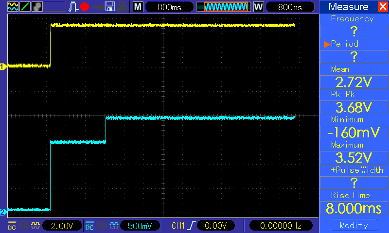
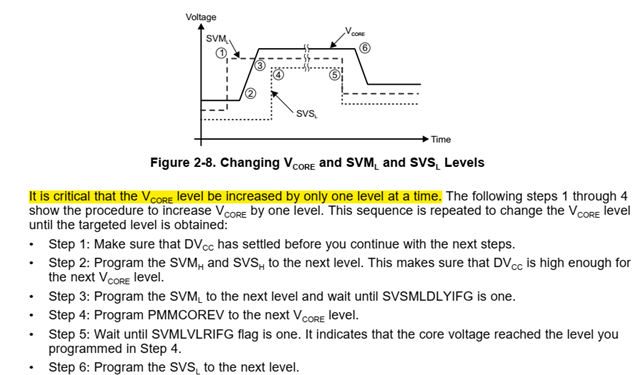
  2. when Temperature was at -25 we checked the Core voltage and it was not at the proper level (1.3V) compared to the Normal condition (1.89V).
  3. The power supply of the system was stable like 3.3V for the MCU.

Also found the below similar concern for MSP430F5310 https://e2e.ti.com/support/microcontrollers/msp-low-power-microcontrollers-group/msp430/f/msp-low-power-microcontroller-forum/977505/msp430f5310-start-up-failures-at-low-temperatures

We could not able to find out the exact reason for this,

Below is the check we made to make sure for concern,

  1. Checked all the power rails for the correct value.
  2. No sudden drop in MCU is observed.
  3. When the Supply is Correct level, the Proper core value is not observed at -25deg.

Please let us know for any Updated and help.

Regards

Rajesh

  • Hi Rajesh,

    It seems that the VCORE stabled at level 0. Like the link you posted, VCORE level should be rise step by step through step 1~6. Could you please do me a favor to catch the waveform to see whether it stuck in level0 and check where the code stuck? 

    Could you please post your function code?

    By the way, what is the quantity of the problem?

  • Hello Allen,

    Please find the Image Core Voltage (CH2) and VCC(CH1) at Normal ambient Condition.

    I will try to capture the Waveforms in thermal chamber at earliest. 

    Please Let me know the behavior of the Core Voltage is right for ambient conditions?

    I m working on HW side and will try to get the function code form the customer as he is working on the Software part.

    Please post technical note or guide if any to understand in more clear.

    few more details on HW side,

    MCU is having 32.768KHz external Crystal. DVCC is connected to 3.3V

    Regards

    Rajesh

  • Hi Rajesh,

    From the waveform, the level rise up from 0 to 3 at one time. It is important to rise step by step if they want a higher VCORE.

    Did customer try to modify the SW(step by step) to see whether it will duplicate?

  • Hello Allen,

    Thanks for the Info,

    Do you mean change the Vcore increase as suggested above in SW and check for the Low temperature performance again?

    Regards

    Rajesh

  • Hi Rajesh,

    Yes, It is a critical procedure recommended in all range temperature. 

  • Hello Allen,

    Please find the attached file for Function code for the same.

    void platform_first_power_up(void) //First Function to call
    {
        /* boot-loader problem workaround: TX pin is set to input state */
        P3DIR &= ~BIT0;
        POWER_DOWN_PIN_INIT;
        /* supply voltage supervisor */
        PMMCTL0_H = PMMPW_H;                /* Open PMM registers for write access */
        SVSMHCTL = SVSHE | SVSHRVL_3 | SVSMHRRL_5;  /* Set SVS/SVM high side level (Vcc) */
        SVSMLCTL = SVSLE | SVMLE | SVSMLRRL_0;      /* Set SVM low side level(core voltage) */
        PMMRIE = SVSHPE;
        UCSCTL6 = XT2OFF;                   /* XT1 On */
        PMMCTL0_H = 0;
    
        WATCHDOG_CLEAR_COUNT;
        usleep(10000);
    
        while(POWER_DOWN_PIN_TEST)
            {
            WATCHDOG_CLEAR_COUNT;
            __delay_cycles(1000);
            }
    
        WATCHDOG_CLEAR_COUNT;
        platform_init();
    }
    
    /* *****************************************************************************
    *
    * *************************************************************************** */
    void platform_init(void) //Second Function to call
    {
    
        platform_power_down = false;
    
        WATCHDOG_CLEAR_COUNT;
    
        /* platform initialization */
        UCSCTL6 = XT2OFF;                       /* XT1 On */
    
        /* Loop until XT1 fault flag is cleared */
        do
        {
            UCSCTL7 &= ~XT1LFOFFG;
            WATCHDOG_CLEAR_COUNT;
        } while (UCSCTL7 & XT1LFOFFG);
    
        /* Core voltage setting */
        platform_set_core_voltage(1);
        platform_set_core_voltage(2);
        platform_set_core_voltage(3);
        __delay_cycles(76563);
    
        /* Initialize DCO to 23.986176 MHz */
        __bis_SR_register(SCG0);
        UCSCTL0 = 0x0000;
        UCSCTL1 = DCORSEL_6;
        UCSCTL2 = FLLD_0 | 731;               /* (731 + 1) * 32768 = 23.986176 MHz */
        UCSCTL5 = DIVPA_3 | DIVA_0 | DIVS_1;  /* ACLK = 32.768 kHz, SMCLK = 11.993088 MHz */
        __bic_SR_register(SCG0);
        __delay_cycles(76563);
    
        /* Loop until XT1, XT2 & DCO fault flag is cleared */
        do
        {
            UCSCTL7 &= ~(XT2OFFG | XT1LFOFFG | DCOFFG);
            SFRIFG1 &= ~OFIFG;
            WATCHDOG_CLEAR_COUNT;
        } while (SFRIFG1 & OFIFG);
    
        PMMCTL0_H = 0;
    
    }
    
    void platform_set_core_voltage (uint8_t level) //Third Function to call
    {
        /* Open PMM registers for write access */
        PMMCTL0_H = PMMPW_H;
    
        /* Make sure no flags are set for iterative sequences */
        while ((PMMIFG & SVSMHDLYIFG) == 0) {};
        while ((PMMIFG & SVSMLDLYIFG) == 0) {};
    
        /* Set SVS/SVM high side new level */
        SVSMHCTL = SVSHE |SVSHRVL_3 | SVMHE | SVSMHRRL_5;
    
        /* Set SVM low side to new level */
        SVSMLCTL = SVSLE | SVMLE | (SVSMLRRL0 * level);
    
        /* Wait till SVM is settled */
        while ((PMMIFG & SVSMLDLYIFG) == 0) {};
    
        /* Clear already set flags */
        PMMIFG &= ~(SVMLVLRIFG | SVMLIFG);
    
        /* Set VCore to new level */
        PMMCTL0_L = (PMMCOREV0 * level);
    
        /* Wait till new level reached */
        if ((PMMIFG & SVMLIFG))
        {
            while ((PMMIFG & SVMLVLRIFG) == 0) {};
        }
    
        /* Set SVS/SVM low side to new level */
        SVSMLCTL = SVSLE | (SVSLRVL0 * level) | SVMLE | (SVSMLRRL0 * level);
    
        /* Lock PMM registers for write access */
        PMMCTL0_H = 0x00;
    }


    Pls guide to proceed further.

    Regards

    Rajesh

  • Hello Allen,

    Any comment on Function code?

    Regards

    Rajesh

  • Hi Rajeshnag,

    The vore setting function looked OK for me. Did customer test that in low temp the vcore increase step by step form level1 to 3 correctly?

    Did customer still duplicate the issue in low temp when try to increase the Vcore step by step?

  • Hello Allen,

    If I'm not wrong,

    According to the function code, the Vcore voltage should rise step by step in all temperature range correct? but i don't see any step by step increase in normal condition as I shared the waveform previously.

    We will try to capture the waveforms in Chamber for confirmation.

    Regards

    Rajesh

  • Hello Allen,

    If I'm not wrong,

    According to the function code, the Vcore voltage should rise step by step in all temperature range correct? but I don't see any step-by-step increase in normal conditions as I shared the waveform previously.

    We will try to capture the waveforms in Chamber for confirmation.

    Regards

    Rajesh

  • Suggest you could debug the code whether it execute every sentence at the same time.

  • Hello Allen,

    For better understanding, If function code is found OK,

    If it is working as expected then we should see/observe the Step by Step increase of core voltage in the ambient conditions also, right? which is not in the current scenario I can see Only One Step increase to 1.9V in ambient conditions.

    Let me know your thoughts.

    Regards

    Rajesh

  • Hi Rajeshnag,

    Yes, in customer code, voltage should be set to level 1 then 2 then 3. But  in the screen shot it increase to 1.9 by one step. This is not the expected performance.

    TI is not aware of any cold start-up problems on these devices. So I guess some configuration in software may not work correctly cause the start-up failure.

    Could you please check the program is proceeding as expected and the performance of the equipment is also in line with expectations?

    Looking forward to your reply.

  • Hello Allen,

    Kindly share any Waveforms for Reference for comparison for VCORE step by Step Increase to verify? whether we are doing it properly or not?

    Regards

    Rajesh

  • Hello Allen,

    With the Code whatever I shared earlier in the conversation being flashed in MCU, I am not seeing the VCORE as step by step as mentioned in the Link. attaching our VCORE Increase (at Normal ambient Condition). attaching PDF with waveform

    Pls, let me know the Power routine function is as recommended?VCORE.pdf

    Regards

    Rajesh

  • Hi Rajeshnag,

    Form your code, it has 3 level step in the initial function.

    platform_set_core_voltage(1);
    platform_set_core_voltage(2);
    platform_set_core_voltage(3);

    In your normal waveform it seems directly go to level3. Why it doesn't do as your code?

    Could you find out where the code stuck, I could try to find the reason.

  • Hello Allen,

    Is there any Hardware Dependency for that?

    We have 0.47uF Termination for that Pin. Attaching the Schematic of the MCU Section for your Reference.

    Regards

    Rajesh

  • Hi Rajesh,

    The Cvcore value is OK, it should be 0.47uF as the recommended value. See in datasheet 5.3

  • Hello Allen,

    Can you Pls Guide me to debugging how to proceed for proper VCORE OUTPUT?

    Regards

    Rajesh

  • Hi Rajesh,

    Enter debug mode and you could add the variables, register value, and all the information you want. Run the program step by step or set breakpoint to see how it goes to check it . 

    How to use debugger in CCS you could refer to 

    http://software-dl.ti.com/ccs/esd/documents/users_guide/ccs_debug-main.html#debug-view

**Attention** This is a public forum