Other Parts Discussed in Thread: MSP-EXP430F5529LP
Hello All, I am new to embedded programming. I started with MSP-EXP430F5529LP and tried to follow a great blog series https://embedded.fm/blog/ese101 by Chris Svec
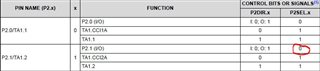
In one of his blogs (https://embedded.fm/blog/ese101-interrupts-blink), the author was using ISR (trigger by a push buttom switch GPIO 1.1) to blink a LED (GPIO 1.0). I follow what he did successfully and then I wanted to create another ISR to use another push buttom switch (GPIO 2.1) to blink another LED (GPIO 4.7).
Following is my code in assembly:
;-------------------------------------------------------------------------------
; Main loop here
;-------------------------------------------------------------------------------
; Set GPIO P1.0 to be an output (P1DIR bit 0 == 1)
BIS.B #0x01, &P1DIR
; Set GPIO P1.1 to be an input (P1DIR bit 1 == 0)
BIC.B #0x02, &P1DIR
; Set GPIO P1.1 to be pulled up or down (P1REN bit 1 == 1)
BIS.B #0x02, &P1REN
; Set GPIO P1.1 as a pull-up resistor (P1OUT bit 1 == 1)
BIS.B #0x02, &P1OUT

; Set interrupt on high-to-low transition of P1.1
BIS.B #0x02, &P1IES
; Clear any interrupts that happened when changing P1IES
BIC.B #0x02, &P1IFG
; Enable P1.1 interrupts
BIS.B #0x02, &P1IE
;-------------------------------------------------------------------------------
; Set GPIO P4.7 to be an output (P4DIR bit 7 == 1)
BIS.B #0x80, &P4DIR
; Set GPIO P2.1 to be an input (P2DIR bit 1 == 0)
BIC.B #0x02, &P2DIR
; Set GPIO P2.1 to be pulled up or down (P2REN bit 1 == 1)
BIS.B #0x02, &P2REN
; Set GPIO P2.1 as a pull-up resistor (P2OUT bit 1 == 1)
BIS.B #0x02, &P2OUT

; Set interrupt on high-to-low transition of P2.1
BIS.B #0x02, &P2IES
; Clear any interrupts that happened when changing P2IES
BIC.B #0x02, &P2IFG
; Enable P2.1 interrupts
BIS.B #0x02, &P2IE

; Enable interrupts
NOP ; the user’s guide recommends a NOP before setting #GIE
BIS #GIE, SR
NOP ; the user’s guide recommends a NOP after setting #GIE

BIC.W #0x01, &P1OUT
BIC.W #0x80, &P4OUT


MainLoop: ; infinite loop that does nothing
JMP MainLoop
NOP

PORT1_ISR:
; Clear the interrupt flag.
BIC #0x02, &P1IFG
; Toggle GPIO P1.0
XOR.B #0x01, &P1OUT
RETI

PORT2_ISR:
; Clear the interrupt flag.
BIC #0x02, &P2IFG
; Toggle GPIO P4.7
XOR.B #0x80, &P4OUT
RETI

;-------------------------------------------------------------------------------
; Stack Pointer definition
;-------------------------------------------------------------------------------
.global __STACK_END
.sect .stack

;-------------------------------------------------------------------------------
; Interrupt Vectors
;-------------------------------------------------------------------------------
.sect ".reset" ; MSP430 RESET Vector
.short RESET
.sect ".int47" ; We added these two lines
.short PORT1_ISR ; for configuring our GPIO Port P1 ISR.

.sect ".int42"
.short PORT2_ISR
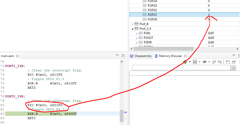
When I run my code on the eval board, it works flawlessly for PORT1_ISR:. ISR PORT1_ISR: is executed when GPIO 1.1 is engaged. It returns to the MainLoop after ISR finishes. However, when I tried PORT2_ISR, GPIO 2.1 triggered the ISR, but upon finishing, it didn't return to the MainLoop. Instead, it keeps looping in this ISR indefinitely. Is there something I did wrong here?
Thanks
Yi