This thread has been locked.

If you have a related question, please click the "Ask a related question" button in the top right corner. The newly created question will be automatically linked to this question.

CCS/MSP430F5529: Can't exit LPM0 and/or ISR. CPU

Part Number: MSP430F5529
Other Parts Discussed in Thread: OPT3001

Tool/software: Code Composer Studio

Hello,

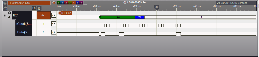
I've been working through DriverLib examples and am trying to develop i2c driver to read/write to opt3001 ALS.  I'm relatively new to understanding interrupt & ISRs and believe I have some issue debugging my code in that at the end i2c_write, the device goes into LPM0+GIE, and the presumably through ISR, but I am unable to to step through OR exit the LPM & corresponding ISR.

Since I am new to interrupts, its distinctly possible that something is not correct with my ISR code, but since I can't step through it I am having a hard time pin pointing what is going wrong.  Line 113 is where I first run into the problem, but i expect that 155 will also have the same problem.

Anything look very wrong?

"MSP430: Can't Single Step Target Program: CPU is currently OFF and debugging capabilities will be limited."

/*
 * i2c_driver.c
 *
 *  Created on: July 16, 2014
 *      Author: a0272990
 *
 *  Copyright 2014 Texas Instruments Incorporated. All rights reserved.
 *
*/

//*****************************************************************************
// #includes
//*****************************************************************************
#include "driverlib.h"
#include "i2c_driver.h"
#include "QmathLib.h"
#include "IQmathLib.h"
#include "math.h"


//*****************************************************************************
// #defines
//*****************************************************************************

#define OPT3001_ADDRESS 0x44    //I2C address for OPT3001

#define CHECK_POLARITY 0x80     //Polarity flag (MSB of MSB)

//*****************************************************************************
// Global Variables
//*****************************************************************************

#define RXCOUNT 0x05
#define TXLENGTH 0x04

uint8_t i2c_transmitCounter = 0;    //Variable to store transmit status for I2C
uint8_t i2c_transmitData[40];        //
uint8_t *p_i2c_transmitData;        //Pointer to transmit data
uint8_t i2c_receivedCounter = 0;     //Variable to store receive status for I2C
uint8_t i2c_receivedBuffer[40];        //
uint8_t *p_i2c_receivedBuffer;        //Pointer to received data

//unsigned char receiveBuffer[10] = { 0x01, 0x01, 0x01, 0x01, 0x01, 0x01, 0x01, 0x01, 0x01, 0x01};
//unsigned char *receiveBufferPointer;
//unsigned char receiveCount = 0;

uint16_t    i2c_mode = 0;               //Variable to store i2c mode (tx or rx)
//*****************************************************************************
// I2C Library functions
//*****************************************************************************
void init_i2c(void)
{

    //Assign I2C pins to USCI_B1
    GPIO_setAsPeripheralModuleFunctionInputPin(GPIO_PORT_P4, GPIO_PIN1 + GPIO_PIN2);

       //Initialize Master
   USCI_B_I2C_initMasterParam param = {0};
   param.selectClockSource = USCI_B_I2C_CLOCKSOURCE_SMCLK;
   param.i2cClk = UCS_getSMCLK();
   param.dataRate = USCI_B_I2C_SET_DATA_RATE_100KBPS;
   USCI_B_I2C_initMaster(USCI_B1_BASE, &param);

   //Enable I2C Module to start operations
   USCI_B_I2C_enable(USCI_B1_BASE);

   //Enable master Receive interrupt
   USCI_B_I2C_enableInterrupt(USCI_B1_BASE, USCI_B_I2C_RECEIVE_INTERRUPT);

}

void i2c_write(uint8_t SLAVE_ADDRESS)
{


    //Initialize Master
    USCI_B_I2C_initMasterParam param = {0};
    param.selectClockSource = USCI_B_I2C_CLOCKSOURCE_SMCLK;
    param.i2cClk = UCS_getSMCLK();
    param.dataRate = USCI_B_I2C_SET_DATA_RATE_400KBPS;
    USCI_B_I2C_initMaster(USCI_B1_BASE, &param);

    //Specify slave address
    USCI_B_I2C_setSlaveAddress(USCI_B1_BASE, SLAVE_ADDRESS
        );

    //Set Transmit mode
    USCI_B_I2C_setMode(USCI_B1_BASE,
        USCI_B_I2C_TRANSMIT_MODE
        );

    //Enable I2C Module to start operations
    USCI_B_I2C_enable(USCI_B1_BASE);


    while (1)
    {
        //Enable transmit Interrupt
        USCI_B_I2C_clearInterrupt(USCI_B1_BASE,  USCI_B_I2C_TRANSMIT_INTERRUPT);
        USCI_B_I2C_enableInterrupt(USCI_B1_BASE, USCI_B_I2C_TRANSMIT_INTERRUPT );

        //Delay between each transaction
        __delay_cycles(50);  //Replace with timer ISR?

        //Load TX byte counter
        i2c_transmitCounter = 1;

        //Initiate start and send first character
        USCI_B_I2C_masterSendMultiByteStart(USCI_B1_BASE, i2c_transmitData[0] );

        //Enter LPM0 with interrupts enabled
        __bis_SR_register(LPM0_bits + GIE);
        __no_operation();

        //Delay until transmission completes
        while (USCI_B_I2C_isBusBusy(USCI_B1_BASE)) ;
    }
}

void i2c_read_byte(uint8_t SLAVE_ADDRESS, uint8_t BYTE_COUNT)
{

      //Initialize Master
      USCI_B_I2C_initMasterParam param = {0};
      param.selectClockSource = USCI_B_I2C_CLOCKSOURCE_SMCLK;
      param.i2cClk = UCS_getSMCLK();
      param.dataRate = USCI_B_I2C_SET_DATA_RATE_100KBPS;
      USCI_B_I2C_initMaster(USCI_B1_BASE, &param);

      //Specify slave address
      USCI_B_I2C_setSlaveAddress(USCI_B1_BASE, SLAVE_ADDRESS);

      //Set receive mode
      USCI_B_I2C_setMode(USCI_B1_BASE, USCI_B_I2C_RECEIVE_MODE);

      //Enable I2C Module to start operations
      USCI_B_I2C_enable(USCI_B1_BASE);

      //Enable master Receive interrupt
      USCI_B_I2C_enableInterrupt(USCI_B1_BASE, USCI_B_I2C_RECEIVE_INTERRUPT);

      //wait for bus to be free
      while (USCI_B_I2C_isBusBusy(USCI_B1_BASE )) ;

      while (1)
      {
          p_i2c_receivedBuffer = (unsigned char *)i2c_receivedBuffer;
          i2c_receivedCounter = sizeof i2c_receivedBuffer;

          //Initialize multi reception
          USCI_B_I2C_masterReceiveMultiByteStart(USCI_B1_BASE);

          //Enter low power mode 0 with interrupts enabled.
          __bis_SR_register(LPM0_bits + GIE);
          __no_operation();
      }
}


void OPT3001_init(void)
{

    uint8_t OPT3001_Config_SW_reset[3] =
    {
        0x01,   //CDC Config register address
        0xC2,   //MSB of configuration (sets 100ms conversion time, single shot mode)
        0x10    //LSB of configuration
    };

    p_i2c_transmitData = (uint8_t *)OPT3001_Config_SW_reset;    //Transmit array start address
    i2c_transmitCounter = sizeof OPT3001_Config_SW_reset;       //Load transmit byte counter
    i2c_write(OPT3001_ADDRESS);
    __delay_cycles(DELAY_10_MS);
}

int32_t OPT3001_singleRead(void)
{

    //uint8_t CDC_Config[2] = {0};    //Test variable
    uint8_t Lux_Meas1_MSB[2] = {0x00,0x00}; //MSBs of capacitance MEAS1
    //uint32_t luxVal=0;

    int32_t Lux_MEAS1 = 0;  //24-bit Lux value from MEAS1 (32bit variable)

    uint8_t OPT3001_initMEAS1[3] =
    {
        0x01,   //OPT Config register address
        0xC2,   //MSB of configuration (sets 100ms conversion time, single shot mode)
        0x10    //LSB of configuration
    };

    const uint8_t OPT3001_ResultAddr[1] = {0x00};   //Lux_MEAS1_MSB register address

    p_i2c_transmitData = (uint8_t *)OPT3001_initMEAS1;      //Transmit array start address
    i2c_transmitCounter = sizeof OPT3001_initMEAS1;         //Load transmit byte counter
    i2c_write(OPT3001_ADDRESS);

    __delay_cycles(DELAY_10_MS);

    p_i2c_transmitData = (uint8_t *)OPT3001_ResultAddr; //Transmit array start address
    i2c_transmitCounter = sizeof OPT3001_ResultAddr;        //Load transmit byte counter
    i2c_write(OPT3001_ADDRESS);

    p_i2c_receivedBuffer = (uint8_t *)Lux_Meas1_MSB;          //Receive array start address
    i2c_read_byte(OPT3001_ADDRESS, sizeof Lux_Meas1_MSB);   //Read two bytes of lux data form result register

    Lux_MEAS1 =  0x0FFF & (uint16_t)Lux_Meas1_MSB[0] << 8 | (uint16_t)Lux_Meas1_MSB[1];
    int8_t exp = Lux_Meas1_MSB[0]>> 4;  //exponent is top four bits
    Lux_MEAS1 = 0.01 * pow(2,exp) * Lux_MEAS1;
    return Lux_MEAS1;
}
//******************************************************************************
//
//This is the USCI_B1 interrupt vector service routine.
//
//******************************************************************************
#if defined(__TI_COMPILER_VERSION__) || defined(__IAR_SYSTEMS_ICC__)
#pragma vector=USCI_B1_VECTOR
__interrupt
#elif defined(__GNUC__)
__attribute__((interrupt(USCI_B1_VECTOR)))
#endif
void USCI_B1_ISR (void)
{
    switch (__even_in_range(UCB1IV,12)){
        case USCI_I2C_UCTXIFG:
        {
            //Check TX byte counter
            if (i2c_transmitCounter < sizeof i2c_transmitData)
            {
                //Initiate send of character from Master to Slave
                USCI_B_I2C_masterSendMultiByteNext(USCI_B1_BASE,
                    i2c_transmitData[i2c_transmitCounter]
                    );

                //Increment TX byte counter
                i2c_transmitCounter++;
            }
            else
            {
                //Initiate stop only
                USCI_B_I2C_masterSendMultiByteStop(USCI_B1_BASE);

                //Clear master interrupt status
                USCI_B_I2C_clearInterrupt(USCI_B1_BASE,
                    USCI_B_I2C_TRANSMIT_INTERRUPT);

                //Exit LPM0 on interrupt return
                __bic_SR_register_on_exit(LPM0_bits);
            }
            break;
        }

        case USCI_I2C_UCRXIFG:
        {
            //Decrement RX byte counter
            i2c_receivedCounter--;

            if (i2c_receivedCounter)
            {
                if (i2c_receivedCounter == 1)
                {
                    //Initiate end of reception -> Receive byte with NAK
                    *p_i2c_receivedBuffer++ =
                        USCI_B_I2C_masterReceiveMultiByteFinish(
                                USCI_B1_BASE
                            );
                }
                else
                {
                    //Keep receiving one byte at a time
                    *p_i2c_receivedBuffer++ = USCI_B_I2C_masterReceiveMultiByteNext(
                            USCI_B1_BASE
                        );
                }
            }
            else
            {
                //Receive last byte
                *p_i2c_receivedBuffer = USCI_B_I2C_masterReceiveMultiByteNext(
                        USCI_B1_BASE
                    );
                __bic_SR_register_on_exit(LPM0_bits);
            }

            break;
        }
    }
}


  • Hi Dan,

    Can you set a breakpoint on line 250 and 284 and does the code break at either of these two locations? (Make sure you set compiler optimiztions = none for proper debugging).
  • I have Optimization Level = off, speedvssize = , inline HW multiply = f5.

    With breakpoints you suggested, it does not even enter the ISR. It locks up after moving into LMP0+GIE
  • Hello Dan,

    Your issue maybe related to the following thread. The issue is the MSPDEBUG stack within CCS has recently changed behavior involving interrupts when single stepping. This behavior will be corrected at some point in the near future. In the meantime, can you try out the fix reported in the link below to see if it solves your issue?

    e2e.ti.com/.../2667628
  • Jace, that may be part of it, but I am still unable to enter ISR.

    while (USCI_B_I2C_isBusBusy(USCI_B1_BASE)) is always returning USCI_B_I2C_BUS_BUSY because the function never enters ISR to call USCI_B_I2C_masterSendMultiByteStop(USCI_B1_BASE)
  • Dan,

    So I'm not sure about setting things up properly with DriverLib, but did you ensure that the I2C specific interrupts are enabled as well as General interrupts? (GEI bit is sys register) You can double check each of these registers when debugging and you are to the point in your code where you are waiting on interrupts.
  • _bis_SR_register(GIE) is called during main() and also as shown above in line 113. It is enabled
    I also checked UCB1IE @ UCTXIE and it is also 1 (I'm stuck during i2c TX right now, so I can't check if UCB1IE @ UCRXIE is correctly enabled).

    The interrupt flag UCB1IFG @ UCTXIFG is not being enabled, instead the NAK Flag is being set. I'm sure that I have correct 7bit slave slave address of 0x44 per datasheet
  • Assuming your first call is to OPT3001_init(), it appears your program will repeatedly send (40-1) bytes:
    > if (i2c_transmitCounter < sizeof i2c_transmitData)

    of 0s:
    > USCI_B_I2C_masterSendMultiByteNext(USCI_B1_BASE,
    > i2c_transmitData[i2c_transmitCounter]

    Forever:
    > while (1)

    The opt3001 data sheet is mute about what happens if you send more than (1+2) bytes of payload. One reasonable response would be a NAK. If it did that, you wouldn't see any more TXIFGs, and the program would stall.
  • I did make one mistake in that the init data that I initially mean to pass is only 3 bytes, but they are declared locally within opt3001_int();  I have updated my code on line 110 to actually make use of p_i2c_transmitData instead of directly passing the configuration bytes.

    USCI_B_I2C_masterSendMultiByteStart(USCI_B1_BASE, *p_i2c_transmitData );

    I also initialized both transmitData & receiveBuffer @ [5] instead of [40];

    I see that UCTXIFG is initially enabled before I go through i2c_write(); where it is disabled, and then the UCNACKIFG is enabled during USCI_B_I2C_masterSendMultiByteStart();

    Bruce,

    Am i misunderstanding that the ISR break; should get me out of the while(1); in i2c_write();? This function with ISR was pulled directly from DriverLib (I did append the case statements of both I2C TX and RX as written in DriverLib)

  • 1) You're trying to use i2c_transmitCounter simultaneously as a count/limit and an index, which are contradictory. Define a separate index variable (or increment the pointer the way you do in the Rx path).
    2) i2c_transmitCounter has the transfer count (at least initially). You shouldn't be comparing against sizeof, since that has no relevance.
    3) "break" is local. A break in one function will not (in itself) cause a break in a loop in a different function. After LPM wakeup, execution continues from the LPM statement. Given the structure of this program, I suggest you remove the while(1) loop(s) entirely.
  • 1.  Ok, I see what you mean.  I changed the ISR to only check for i2c_transmit count != 0

    2. Along with Number 1, I changed concept to take sizeof the data that is supposed to be TX or RX  & decrement counter until no bytes are left.

    3.  Also make sense, I removed it.  Here is the updated code.  

    /*
     * i2c_driver.c
     *
     *  Created on: July 16, 2014
     *      Author: a0272990
     *
     *  Copyright 2014 Texas Instruments Incorporated. All rights reserved.
     *
    */
    
    //*****************************************************************************
    // #includes
    //*****************************************************************************
    #include "driverlib.h"
    #include "i2c_driver.h"
    #include "QmathLib.h"
    #include "IQmathLib.h"
    #include "math.h"


    //*****************************************************************************
    // #defines
    //*****************************************************************************
    
    #define OPT3001_ADDRESS 0x44    //I2C address for OPT3001
    
    #define CHECK_POLARITY 0x80     //Polarity flag (MSB of MSB)
    
    //*****************************************************************************
    // Global Variables
    //*****************************************************************************
    
    #define RXCOUNT 0x05
    #define TXLENGTH 0x04
    
    uint8_t i2c_transmitCounter = 0;    //Variable to store transmit status for I2C
    uint8_t i2c_transmitData[5];        //
    uint8_t *p_i2c_transmitData;        //Pointer to transmit data
    uint8_t i2c_receivedCounter = 0;     //Variable to store receive status for I2C
    uint8_t i2c_receivedBuffer[40];        //
    uint8_t *p_i2c_receivedBuffer;        //Pointer to received data
    
    //unsigned char receiveBuffer[10] = { 0x01, 0x01, 0x01, 0x01, 0x01, 0x01, 0x01, 0x01, 0x01, 0x01};
    //unsigned char *receiveBufferPointer;
    //unsigned char receiveCount = 0;
    
    uint16_t    i2c_mode = 0;               //Variable to store i2c mode (tx or rx)
    //*****************************************************************************
    // I2C Library functions
    //*****************************************************************************
    void init_i2c(void)
    {
    
        //Assign I2C pins to USCI_B1
        GPIO_setAsPeripheralModuleFunctionInputPin(GPIO_PORT_P4, GPIO_PIN1 + GPIO_PIN2);
    
           //Initialize Master
       USCI_B_I2C_initMasterParam param = {0};
       param.selectClockSource = USCI_B_I2C_CLOCKSOURCE_SMCLK;
       param.i2cClk = UCS_getSMCLK();
       param.dataRate = USCI_B_I2C_SET_DATA_RATE_100KBPS;
       USCI_B_I2C_initMaster(USCI_B1_BASE, &param);
    
       //Enable I2C Module to start operations
       USCI_B_I2C_enable(USCI_B1_BASE);
    
       //Enable master Receive interrupt
       USCI_B_I2C_enableInterrupt(USCI_B1_BASE, USCI_B_I2C_RECEIVE_INTERRUPT);
    
    }
    
    void i2c_write(uint8_t SLAVE_ADDRESS)
    {
    
    
        //Initialize Master
        USCI_B_I2C_initMasterParam param = {0};
        param.selectClockSource = USCI_B_I2C_CLOCKSOURCE_SMCLK;
        param.i2cClk = UCS_getSMCLK();
        param.dataRate = USCI_B_I2C_SET_DATA_RATE_400KBPS;
        USCI_B_I2C_initMaster(USCI_B1_BASE, &param);
    
        uint8_t SL_ADDR_WR = ((SLAVE_ADDRESS<<1)); // shift address left.  Write bit enable = 0
    
        //Specify slave address
        USCI_B_I2C_setSlaveAddress(USCI_B1_BASE, SL_ADDR_WR
            );
    
        //Set Transmit mode
        USCI_B_I2C_setMode(USCI_B1_BASE,
            USCI_B_I2C_TRANSMIT_MODE
            );
    
        //Enable I2C Module to start operations
        USCI_B_I2C_enable(USCI_B1_BASE);
    
        //Enable transmit Interrupt
        USCI_B_I2C_clearInterrupt(USCI_B1_BASE,  USCI_B_I2C_TRANSMIT_INTERRUPT + USCI_B_I2C_NAK_INTERRUPT);
        USCI_B_I2C_enableInterrupt(USCI_B1_BASE, USCI_B_I2C_TRANSMIT_INTERRUPT);
    
        //Delay between each transaction
        __delay_cycles(50);  //Replace with timer ISR?
    
    
        //Initiate start and send first character
        USCI_B_I2C_masterSendMultiByteStart(USCI_B1_BASE, *p_i2c_transmitData++ ); //p_i2c_data is first address of data packet. assigned in opt3001_init();
    
        i2c_transmitCounter--;
    
        //Interrupts enabled
       __bis_SR_register(GIE); //LPM0_bits + GIE
       __no_operation();
    
    
        //Delay until transmission completes
        while (USCI_B_I2C_isBusBusy(USCI_B1_BASE)) ;
    
    }
    
    void i2c_read_byte(uint8_t SLAVE_ADDRESS, uint8_t BYTE_COUNT)
    {
    
          //Initialize Master
          USCI_B_I2C_initMasterParam param = {0};
          param.selectClockSource = USCI_B_I2C_CLOCKSOURCE_SMCLK;
          param.i2cClk = UCS_getSMCLK();
          param.dataRate = USCI_B_I2C_SET_DATA_RATE_100KBPS;
          USCI_B_I2C_initMaster(USCI_B1_BASE, &param);
    
          //Specify slave address
          uint8_t SL_ADDR_R = ((SLAVE_ADDRESS<<1) | 0x01 ); //left shift address & add read bit
          USCI_B_I2C_setSlaveAddress(USCI_B1_BASE, SLAVE_ADDRESS);
    
          //Set receive mode
          USCI_B_I2C_setMode(USCI_B1_BASE, USCI_B_I2C_RECEIVE_MODE);
    
          //Enable I2C Module to start operations
          USCI_B_I2C_enable(USCI_B1_BASE);
    
          //Enable master Receive interrupt
          USCI_B_I2C_enableInterrupt(USCI_B1_BASE, USCI_B_I2C_RECEIVE_INTERRUPT);
    
          //wait for bus to be free
          while (USCI_B_I2C_isBusBusy(USCI_B1_BASE )) ;
    
          while (1)
          {
              p_i2c_receivedBuffer = (unsigned char *)i2c_receivedBuffer;
              i2c_receivedCounter = sizeof i2c_receivedBuffer;
    
              //Initialize multi reception
              USCI_B_I2C_masterReceiveMultiByteStart(USCI_B1_BASE);
    
              //Enter low power mode 0 with interrupts enabled.
              //__bis_SR_register(GIE); //LPM0_bits + GIE
              __no_operation();
          }
    }
    
    
    void OPT3001_init(void)
    {
    
        uint8_t OPT3001_Config_SW_reset[3] =
        {
            0x01,   //CDC Config register address
            0xC2,   //MSB of configuration (sets 100ms conversion time, single shot mode)
            0x10    //LSB of configuration
        };
    
        p_i2c_transmitData = (uint8_t *)OPT3001_Config_SW_reset;    //Transmit array start address
        i2c_transmitCounter = sizeof OPT3001_Config_SW_reset;       //Load transmit byte counter
        i2c_write(OPT3001_ADDRESS);
        __delay_cycles(DELAY_10_MS);
    }
    
    int32_t OPT3001_singleRead(void)
    {
    
        //uint8_t CDC_Config[2] = {0};    //Test variable
        uint8_t Lux_Meas1_MSB[2] = {0x00,0x00}; //MSBs of capacitance MEAS1
        //uint32_t luxVal=0;
    
        int32_t Lux_MEAS1 = 0;  //24-bit Lux value from MEAS1 (32bit variable)
    
        uint8_t OPT3001_initMEAS1[3] =
        {
            0x01,   //OPT Config register address
            0xC4,   //MSB of configuration (sets 100ms conversion time, continuous conversion
            0x10    //LSB of configuration
        };
    
        const uint8_t OPT3001_ResultAddr[1] = {0x00};   //Lux_MEAS1_MSB register address
    
        p_i2c_transmitData = (uint8_t *)OPT3001_initMEAS1;      //Transmit array start address
        i2c_transmitCounter = sizeof OPT3001_initMEAS1;         //Load transmit byte counter
        i2c_write(OPT3001_ADDRESS);
    
        __delay_cycles(DELAY_10_MS);
    
        p_i2c_transmitData = (uint8_t *)OPT3001_ResultAddr; //Transmit array start address
        i2c_transmitCounter = sizeof OPT3001_ResultAddr;        //Load transmit byte counter
        i2c_write(OPT3001_ADDRESS);
    
        p_i2c_receivedBuffer = (uint8_t *)Lux_Meas1_MSB;          //Receive array start address
        i2c_read_byte(OPT3001_ADDRESS, sizeof Lux_Meas1_MSB);   //Read two bytes of lux data form result register
    
        Lux_MEAS1 =  0x0FFF & (uint16_t)Lux_Meas1_MSB[0] << 8 | (uint16_t)Lux_Meas1_MSB[1];
        int8_t exp = Lux_Meas1_MSB[0]>> 4;  //exponent is top four bits
        Lux_MEAS1 = 0.01 * pow(2,exp) * Lux_MEAS1;
        return Lux_MEAS1;
    }
    //******************************************************************************
    //
    //This is the USCI_B1 interrupt vector service routine.
    //
    //******************************************************************************
    #if defined(__TI_COMPILER_VERSION__) || defined(__IAR_SYSTEMS_ICC__)
    #pragma vector=USCI_B1_VECTOR
    __interrupt
    #elif defined(__GNUC__)
    __attribute__((interrupt(USCI_B1_VECTOR)))
    #endif
    void USCI_B1_ISR (void)
    {
        switch (__even_in_range(UCB1IV,12)){
            case USCI_I2C_UCTXIFG:
            {
                //Check TX byte counter
                if (i2c_transmitCounter)
                {
                    //Initiate send of character from Master to Slave
                    USCI_B_I2C_masterSendMultiByteNext(USCI_B1_BASE,
                        *p_i2c_transmitData++
                        );
    
                    //Increment TX byte counter
                    i2c_transmitCounter--;
                }
                else
                {
                    //Initiate stop only
                    USCI_B_I2C_masterSendMultiByteStop(USCI_B1_BASE);
    
                    //Clear master interrupt status
                    USCI_B_I2C_clearInterrupt(USCI_B1_BASE,
                        USCI_B_I2C_TRANSMIT_INTERRUPT);
    
                    //Exit LPM0 on interrupt return
                    //__bic_SR_register_on_exit(LPM0_bits);  Not in low power mode
                }
                break;
            }
    
            case USCI_I2C_UCRXIFG:
            {
                //Decrement RX byte counter
                i2c_receivedCounter--;
    
                if (i2c_receivedCounter)
                {
                    if (i2c_receivedCounter == 1)
                    {
                        //Initiate end of reception -> Receive byte with NAK
                        *p_i2c_receivedBuffer++ =
                            USCI_B_I2C_masterReceiveMultiByteFinish(
                                    USCI_B1_BASE
                                );
                    }
                    else
                    {
                        //Keep receiving one byte at a time
                        *p_i2c_receivedBuffer++ = USCI_B_I2C_masterReceiveMultiByteNext(
                                USCI_B1_BASE
                            );
                    }
                }
                else
                {
                    //Receive last byte
                    *p_i2c_receivedBuffer = USCI_B_I2C_masterReceiveMultiByteNext(
                            USCI_B1_BASE
                        );
                    //__bic_SR_register_on_exit(LPM0_bits); not in low power mode
                }
    
                break;
            }
        }
    }


  • > uint8_t SL_ADDR_WR = ((SLAVE_ADDRESS<<1)); // shift address left. Write bit enable = 0
    You shouldn't do this. setSlaveAddress expects a 7-bit address (UCB1I2CSA), and 0x44 looks fine for that.
  • You're right.  I did that as a test to see if that was an issue.  It was not.

    A Few things I observe:

    1. UCTXIFG is 1 at debug launch.  It gets disabled during interrupt clears (seems normal).  

    2. As I step through I2c_materSendMultiByteStart();  UCTXIFG ends up being re-enabled at stage "while (!(HWREG8(baseAddress + OFS_UCBxIFG) & UCTXIFG)) ;" (in usci_b_i2c.c, line 15 below)

    3. The very next step, is HWREG8(baseAddress + OFS_UCBxTXBUF) = txData; (again, in usci_b_i2c.c) and the UCTXIFG is again disabled.   This assignment is loading the first byte of TX data into TXBUF.  Register UCB1TXBUF show the correct value of the first byte from transmitData (line 18 below)

    Data Capture down below.  I'm actually getting a NACK Flag in register, but it doesn't show up in data capture.  Maybe I need a new topic, but I still do not understand why UCTXIFG is no getting enabled when there is data loaded into UCB1TXBUF


    void USCI_B_I2C_masterSendMultiByteStart (uint16_t baseAddress, uint8_t txData ) { //Store current transmit interrupt enable uint8_t txieStatus = HWREG8(baseAddress + OFS_UCBxIE) & UCTXIE; //Disable transmit interrupt enable HWREG8(baseAddress + OFS_UCBxIE) &= ~(UCTXIE); //Send start condition. HWREG8(baseAddress + OFS_UCBxCTL1) |= UCTR + UCTXSTT; //Poll for transmit interrupt flag. while (!(HWREG8(baseAddress + OFS_UCBxIFG) & UCTXIFG)) ; //Send single byte data. HWREG8(baseAddress + OFS_UCBxTXBUF) = txData; //Reinstate transmit interrupt enable HWREG8(baseAddress + OFS_UCBxIE) |= txieStatus; }

  • If you're debug-stepping through the transaction, keep in mind that the OPT3001 enforces a 28ms timeout (SCL low). The I2C unit holds (stretches) SCL low when it's waiting for a Tx byte to be loaded into TXBUF, which is presumably the state at the end of your analyzer trace.
  • I think the debug stepping may have been one of the main problems.  Depending on where you set breakpoints, the TXIFG may not trigger correctly. I found this out by letting code run without breakpoints and see all the expected data in the i2c analyzer.

    I seem to have it working now, however I did find that there is a few bugs in the TIDA 00754 where the MSBs are not properly being assigned into the correct variable.  In any case, here is the final code.  I did have to adjust the RXCOUNT to a fixed 2 bytes in order to avoid getting stuck in an RX loop.

    I would like to get this into continuous mode rather than 1shot, but that's a problem for another day.

    /*
     * i2c_driver.c
     *
     *  Created on: July 16, 2014
     *      Author: a0272990
     *
     *  Copyright 2014 Texas Instruments Incorporated. All rights reserved.
     *
    */
    
    //*****************************************************************************
    // #includes
    //*****************************************************************************
    #include "driverlib.h"
    #include "i2c_driver.h"
    #include "QmathLib.h"
    #include "IQmathLib.h"
    #include "math.h"


    //*****************************************************************************
    // #defines
    //*****************************************************************************
    
    #define OPT3001_ADDRESS 0x44    //I2C address for OPT3001
    
    #define CHECK_POLARITY 0x80     //Polarity flag (MSB of MSB)
    
    //*****************************************************************************
    // Global Variables
    //*****************************************************************************
    
    #define RXCOUNT 0x02  // expected length of opt3001 register read
    #define TXLENGTH 0x04
    
    uint8_t i2c_transmitCounter = 0;    //Variable to store transmit status for I2C
    uint8_t i2c_transmitData[5];        //
    uint8_t *p_i2c_transmitData;        //Pointer to transmit data
    uint8_t i2c_receivedCounter = 0;     //Variable to store receive status for I2C
    uint8_t i2c_receivedBuffer[2];        // Only works for opt3001
    uint8_t *p_i2c_receivedBuffer;        //Pointer to received data
    
    //unsigned char receiveBuffer[10] = { 0x01, 0x01, 0x01, 0x01, 0x01, 0x01, 0x01, 0x01, 0x01, 0x01};
    //unsigned char *receiveBufferPointer;
    //unsigned char receiveCount = 0;
    
    uint16_t    i2c_mode = 0;               //Variable to store i2c mode (tx or rx)
    //*****************************************************************************
    // I2C Library functions
    //*****************************************************************************
    void init_i2c(void)
    {
    
        //Assign I2C pins to USCI_B1
        GPIO_setAsPeripheralModuleFunctionInputPin(GPIO_PORT_P4, GPIO_PIN1 + GPIO_PIN2);
    
           //Initialize Master
       USCI_B_I2C_initMasterParam param = {0};
       param.selectClockSource = USCI_B_I2C_CLOCKSOURCE_SMCLK;
       param.i2cClk = UCS_getSMCLK();
       param.dataRate = USCI_B_I2C_SET_DATA_RATE_100KBPS;
       USCI_B_I2C_initMaster(USCI_B1_BASE, &param);
    
       //Enable I2C Module to start operations
       USCI_B_I2C_enable(USCI_B1_BASE);
    
       //Enable master Receive interrupt
       USCI_B_I2C_enableInterrupt(USCI_B1_BASE, USCI_B_I2C_RECEIVE_INTERRUPT);
    
    }
    
    void i2c_write(uint8_t SLAVE_ADDRESS)
    {
    
    
        //Initialize Master
        USCI_B_I2C_initMasterParam param = {0};
        param.selectClockSource = USCI_B_I2C_CLOCKSOURCE_SMCLK;
        param.i2cClk = UCS_getSMCLK();
        param.dataRate = USCI_B_I2C_SET_DATA_RATE_400KBPS;
        USCI_B_I2C_initMaster(USCI_B1_BASE, &param);
    
        //uint8_t SL_ADDR_WR = ((SLAVE_ADDRESS<<1)); // shift address left.  Write bit enable = 0
    
        //Specify slave address
        USCI_B_I2C_setSlaveAddress(USCI_B1_BASE, SLAVE_ADDRESS
            );
    
        //Set Transmit mode
        USCI_B_I2C_setMode(USCI_B1_BASE,
            USCI_B_I2C_TRANSMIT_MODE
            );
    
        //Enable I2C Module to start operations
        USCI_B_I2C_enable(USCI_B1_BASE);
    
        //Enable transmit Interrupt
        USCI_B_I2C_clearInterrupt(USCI_B1_BASE,  USCI_B_I2C_TRANSMIT_INTERRUPT + USCI_B_I2C_NAK_INTERRUPT);
        USCI_B_I2C_enableInterrupt(USCI_B1_BASE, USCI_B_I2C_TRANSMIT_INTERRUPT);
    
        //Delay between each transaction
        __delay_cycles(50);  //Replace with timer ISR?
    
    
        //Initiate start and send first character
        USCI_B_I2C_masterSendMultiByteStart(USCI_B1_BASE, *p_i2c_transmitData++ ); //p_i2c_data is first address of data packet. assigned in opt3001_init();
    
        i2c_transmitCounter--;
    
        //Interrupts enabled
       __bis_SR_register(GIE); //LPM0_bits + GIE
       __no_operation();
    
    
        //Delay until transmission completes
        while (USCI_B_I2C_isBusBusy(USCI_B1_BASE)) ;
    
    }
    
    void i2c_read_byte(uint8_t SLAVE_ADDRESS, uint8_t BYTE_COUNT)
    {
    
          //Initialize Master
          USCI_B_I2C_initMasterParam param = {0};
          param.selectClockSource = USCI_B_I2C_CLOCKSOURCE_SMCLK;
          param.i2cClk = UCS_getSMCLK();
          param.dataRate = USCI_B_I2C_SET_DATA_RATE_100KBPS;
          USCI_B_I2C_initMaster(USCI_B1_BASE, &param);
    
          //Specify slave address. USE 7BIT SLAVE ADDR
          USCI_B_I2C_setSlaveAddress(USCI_B1_BASE, SLAVE_ADDRESS);
    
          //Set receive mode
          USCI_B_I2C_setMode(USCI_B1_BASE, USCI_B_I2C_RECEIVE_MODE);
    
          //Enable I2C Module to start operations
          USCI_B_I2C_enable(USCI_B1_BASE);
    
          //Enable master Receive interrupt
          USCI_B_I2C_enableInterrupt(USCI_B1_BASE, USCI_B_I2C_RECEIVE_INTERRUPT);
    
          //wait for bus to be free
          while (USCI_B_I2C_isBusBusy(USCI_B1_BASE )) ;
    
          p_i2c_receivedBuffer = (unsigned char *)i2c_receivedBuffer;
          i2c_receivedCounter = RXCOUNT;
    
          //Initialize multi reception
          USCI_B_I2C_masterReceiveMultiByteStart(USCI_B1_BASE);
    
          //Enter low power mode 0 with interrupts enabled.
         __bis_SR_register(GIE); //LPM0_bits + GIE
          __no_operation();
    
    }
    
    
    void OPT3001_init(void)
    {
    
        uint8_t OPT3001_Config_SW_reset[3] =
        {
            0x01,   //CDC Config register address
            0xC2,   //MSB of configuration (sets 100ms conversion time, single shot mode)
            0x10    //LSB of configuration
        };
    
        p_i2c_transmitData = (uint8_t *)OPT3001_Config_SW_reset;    //Transmit array start address
        i2c_transmitCounter = sizeof OPT3001_Config_SW_reset;       //Load transmit byte counter
        i2c_write(OPT3001_ADDRESS);
        __delay_cycles(DELAY_10_MS);
    }
    
    int32_t OPT3001_singleRead(void)
    {
    
        //uint8_t CDC_Config[2] = {0};    //Test variable
        uint8_t Lux_Meas1_MSB[2] = {0x00,0x00}; //MSBs of capacitance MEAS1
        //uint32_t luxVal=0;
    
        int32_t Lux_MEAS1 = 0;  //24-bit Lux value from MEAS1 (32bit variable)
    
        uint8_t OPT3001_initMEAS1[3] =
        {
            0x01,   //OPT Config register address
            0xC2,   //MSB of configuration (sets 100ms conversion time, continuous conversion
            0x10    //LSB of configuration
        };
    
        const uint8_t OPT3001_ResultAddr[1] = {0x00};   //Lux_MEAS1_MSB register address
    
        p_i2c_transmitData = (uint8_t *)OPT3001_initMEAS1;      //Transmit array start address
        i2c_transmitCounter = sizeof OPT3001_initMEAS1;         //Load transmit byte counter
        i2c_write(OPT3001_ADDRESS);
    
        __delay_cycles(DELAY_10_MS);
    
        p_i2c_transmitData = (uint8_t *)OPT3001_ResultAddr; //Transmit array start address
        i2c_transmitCounter = sizeof OPT3001_ResultAddr;        //Load transmit byte counter
        i2c_write(OPT3001_ADDRESS);
    
        p_i2c_receivedBuffer = (uint8_t *)Lux_Meas1_MSB;          //Receive array start address
        i2c_read_byte(OPT3001_ADDRESS, sizeof Lux_Meas1_MSB);   //Read two bytes of lux data form result register
        Lux_Meas1_MSB[0] = i2c_receivedBuffer[0];
        Lux_Meas1_MSB[1] = i2c_receivedBuffer[1];
    
        Lux_MEAS1 =  0x0FFF & (uint16_t)Lux_Meas1_MSB[0] << 8 | (uint16_t)Lux_Meas1_MSB[1];
        int8_t exp = Lux_Meas1_MSB[0]>> 4;  //exponent is top four bits
        Lux_MEAS1 = 0.01 * pow(2,exp) * Lux_MEAS1;
        return Lux_MEAS1;
    }
    
    int32_t OPT3001_ID(uint8_t OPT_ID_TYPE)
    {
    
        uint8_t readID_MSB[2] =  {0x00,0x00};
    
        //Was already configured at this point by opt3001_int();
        uint8_t OPT3001_initMEAS1[3] =
        {
            0x01,   //OPT Config register address
            0xC2,   //MSB of configuration (sets 100ms conversion time, continuous conversion
            0x10    //LSB of configuration
        };
    
        p_i2c_transmitData = (uint8_t *)OPT3001_initMEAS1;      //Transmit array start address
        i2c_transmitCounter = sizeof OPT3001_initMEAS1;         //Load transmit byte counter
        i2c_write(OPT3001_ADDRESS);
    
        __delay_cycles(DELAY_10_MS);
    
        p_i2c_transmitData = (uint8_t *)OPT_ID_TYPE; //Transmit array start address
        i2c_transmitCounter = sizeof OPT_ID_TYPE;        //Load transmit byte counter
        i2c_write(OPT3001_ADDRESS);
    
        p_i2c_receivedBuffer = (uint8_t *)readID_MSB;          //Receive array start address
        i2c_read_byte(OPT3001_ADDRESS, sizeof readID_MSB);   //Read two bytes of lux data form result register
        uint32_t readID = 0x0FFF & (uint16_t)readID_MSB[0] << 8 | (uint16_t)readID_MSB[1];
        return readID;
    
    }
    //******************************************************************************
    //
    //This is the USCI_B1 interrupt vector service routine.
    //
    //******************************************************************************
    #if defined(__TI_COMPILER_VERSION__) || defined(__IAR_SYSTEMS_ICC__)
    #pragma vector=USCI_B1_VECTOR
    __interrupt
    #elif defined(__GNUC__)
    __attribute__((interrupt(USCI_B1_VECTOR)))
    #endif
    void USCI_B1_ISR (void)
    {
        switch (__even_in_range(UCB1IV,12)){
            case USCI_I2C_UCTXIFG:
            {
                //Check TX byte counter
                if (i2c_transmitCounter)
                {
                    //Initiate send of character from Master to Slave
                    USCI_B_I2C_masterSendMultiByteNext(USCI_B1_BASE,
                        *p_i2c_transmitData++
                        );
    
                    //Increment TX byte counter
                    i2c_transmitCounter--;
                }
                else
                {
                    //Initiate stop only
                    USCI_B_I2C_masterSendMultiByteStop(USCI_B1_BASE);
    
                    //Clear master interrupt status
                    USCI_B_I2C_clearInterrupt(USCI_B1_BASE,
                        USCI_B_I2C_TRANSMIT_INTERRUPT);
    
                    //Exit LPM0 on interrupt return
                    //__bic_SR_register_on_exit(LPM0_bits);  Not in low power mode
                }
                break;
            }
    
            case USCI_I2C_UCRXIFG:
            {
                //Decrement RX byte counter
                i2c_receivedCounter--;
    
                if (i2c_receivedCounter)
                {
                    if (i2c_receivedCounter == 1)
                    {
                        //Initiate end of reception -> Receive byte with NAK
                        *p_i2c_receivedBuffer++ =   USCI_B_I2C_masterReceiveMultiByteFinish( USCI_B1_BASE );
                    }
                    else
                    {
                        //Keep receiving one byte at a time
                        *p_i2c_receivedBuffer++ = USCI_B_I2C_masterReceiveMultiByteNext( USCI_B1_BASE );
                    }
                }
                else
                {
                    //Receive last byte
                    *p_i2c_receivedBuffer = USCI_B_I2C_masterReceiveMultiByteNext( USCI_B1_BASE );
                    __bic_SR_register_on_exit(LPM0_bits); //not in low power mode
                }
    
                break;
            }
        }
    }


**Attention** This is a public forum