Part Number: MSP430F149
Hi team,
Issue:
The ipp of msp430f149, which is currently in debug phase, the customer has written the simple boot file and app file, and has also included the interrupt jump instruction in the boot file. If there are no interrupts in the app file, the program can execute, and once the serial receive interrupt is turned on in the app program, the program stops after the serial send instruction. The serial interrupt vector is also redefined in the boot program.
The customer would like to know what's the possible reason for that, is it related to the app interrupts program?
The boot program is as follows:
#include "io430.h"
#include "flash.h"
void USART_Init(void);
void main( void )
{
char i=0;
WDTCTL = WDTPW + WDTHOLD;
flash_init();
USART_Init();
while(1)
{
while (IFG1 & URXIFG0)
{
rec[i]=RXBUF0;
i++;
if(i==count)
{
i=0;
flash_write(rec);
asm(" br &0x8100;");//Jump after receiving the upgrade
}
}
}
}
void USART_Init(void)
{
P3SEL |= BIT4+BIT5; // P3.4,5 is selected as the UART transceiver port
ME1 |= UTXE0 + URXE0; // Enable USART0 transmit and receive
UCTL0 |= CHAR; // 8-bit character
UTCTL0 |= SSEL0; // UCLK = ACLK
UBR00 = 0x03; // 32k/9600 - 3.41
UBR10 = 0x00; //
UMCTL0 = 0x4A; // Modulation
UCTL0 &= ~SWRST; // Initialize the UART0 state machine
IE1 |= URXIE0; // Enable to receive interrupts
// _EINT();
}
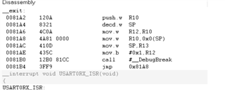
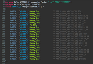
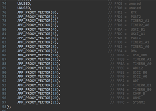
#pragma vector=USART0RX_VECTOR
__interrupt void USART0RX_ISR(void)
{
asm(" br &0x81A2;");//Serial interrupt redefined
}
App program is as follows:
#include "msp430x14x.h"
#define CPU_F ((double)8000000)   //Accurate time delay
#define delay_us(x) __delay_cycles((long)(CPU_F*(double)x/1000000.0))
#define delay_ms(x) __delay_cycles((long)(CPU_F*(double)x/1000.0))
void USART_Init(void);

void main( void )
{
  WDTCTL = WDTPW + WDTHOLD;


   BCSCTL1 &= ~XT2OFF;                 //Turn on the XT2 high-frequency crystal oscillator
  do
  {
    IFG1 &= ~OFIFG;                 //Clear the crystal fail flag
    for (char z = 0xFF; z > 0; z--);     //Wait for the 8-MHz crystal to oscillation
  }
  while ((IFG1 & OFIFG));             //Crystal failure flag still present?
  BCSCTL2 |= SELM_2 + SELS;           //MCLK and SMCLK select high frequency crystal
  USART_Init();
  P2DIR|=0XFF;
  P2OUT=0X00;
  delay_ms(2000);
  P2OUT=0Xff;
  delay_ms(2000);
  P2OUT=0X00;
  while(1)
  {
    LPM0;
  }

}
#pragma vector=USART0RX_VECTOR
__interrupt void USART0RX_ISR(void)
{
  char r;
  r=RXBUF0;
  P2OUT^=0xFF;

}
void USART_Init(void)
{
    P3SEL |= 0x30;                            // P3.4,5 is selected as the UART transceiver port
    ME1 |= UTXE0 + URXE0;                     // Enable USART0 transmit and receive
    UCTL0 |= CHAR;                            // 8-bit character
    UTCTL0 |= SSEL0;                          // UCLK = ACLK
    UBR00 = 0x03;                             // 32k/9600 - 3.41
    UBR10 = 0x00;                             //
    UMCTL0 = 0x4A;                            // Modulation
    UCTL0 &= ~SWRST;                          // Initialize the UART0 state machine
    IE1 |= URXIE0;                            // Enable to receive interrupts
    _EINT();
}
Could you help check this issue? Thanks.
Best Regards,
Cherry