This thread has been locked.

If you have a related question, please click the "Ask a related question" button in the top right corner. The newly created question will be automatically linked to this question.

MSP430AFE253: Setup and Avoiding Synchronization Error

Part Number: MSP430AFE253
Other Parts Discussed in Thread: MSP-EXP430F5529LP

Hello,

I'm currently trying to use this chip (for the first time) in a design of mine, but am having trouble flashing any code onto the chip without getting a synchronization error back. My setup consists of a simple breakout PCB with just the MCU (and a disconnected clock module) on it, connected via an FTDI USB-to-serial adapter (FT232RL). I have a simple sketch from the Resource Explorer designed for the chip that I am uploading in a post-build step in code composer studio, but no luck so far. Is there something that I am missing in this setup, or some other components that might make this process easier? Any advice would be appreciated.

(my setup is also described more in depth in this thread: https://e2e.ti.com/support/microcontrollers/msp-low-power-microcontrollers-group/msp430/f/msp-low-power-microcontroller-forum/1093421/msp430afe253-msp430afe2xx-issue-connecting-to-an-external-oscillator)

The error reads as follows:

MSP430 Bootstrap Loader Communication Program (Version 2.01c)
Number of mass erase cycles set to 1.
Mass Erase...
ERROR: Synchronization failed!
Device with boot loader connected?
makefile:164: recipe for target 'post-build' failed
gmake[2]: [post-build] Error 1 (ignored)

  • Hi Sam,

    I responded to your other posting with some information and suggestions.  After some additional searching I found something very interesting.  Apparently this person was able to make a modified version of the bsl-scripter program that he claims will no allow it to work with any USB to UART adapter.  You might want check this out.  I have one of our other engineers looking into this as well to see if he can verify it works.

    https://forum.43oh.com/topic/13429-modified-bsl-scripter-for-windows-now-works-with-ftdi-and-other-usb-to-uart-adapters/

  • Hi Dennis,

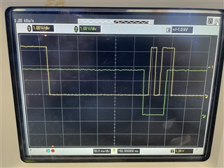
    I believe my connections are the same as those specified in the Flash BSL Guide, although the pin specifications of P1.1 and P2.2 or Rx and Tx don't match the pinout on the datasheet of the AFE253 (they appear to be P1.4 and P1.3 respectively). The output of the DTR and RTS pins also appear to be working correctly, but I have provided the scope capture of both for you to take a look at. Channel 2 (green) is the DTR -> RST line and channel 1 (yellow) is RTS -> TEST. I have shifted the DTR output down for clarity.


    As for the modified BSL scripter, it does look promising, but from my understanding the AFE253 is a member of the F2xx family which would use BSLDEMO in place of the modified BSL-scripter? This would point me in the direction of this repository for BSLDEMO2.01c, which gave me the above invocation sequence. Would it be worth trying to use the BSL-scripter version here?

  • One thing worth noting is that the DTR line goes low a second time about 900 ms after the first drop. I'm not sure if this is intended or if it is related to the synchronization error (either cause or effect), but it could be something?

  • Hi Sam,

    The scope signals look like what I would expect to put the target into BSL mode

    Regarding BSL scripter, I would say its worthing trying, but I cannot say with certainty that it will work.

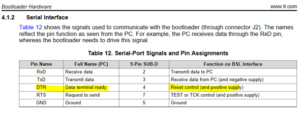
    Regarding the DTR line, this is noteworthy because this signal is connected to the target's RESET pin and would force the device out of BSL mode.

  • That was what I was afraid of :( 

    Do you have an idea of what might be causing this issue? Possibly the use of BSLDEMO in a 'post-build' step of CCS, or an errant command in the post build command ('BSLDEMO-2.01c.exe -cCOM14 -m1 -ijevpr *filename*.txt') itself?

  • Hi Dennis,

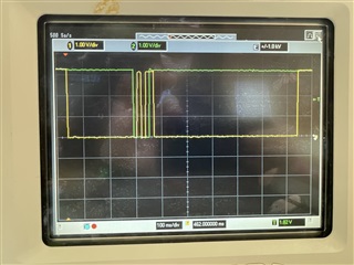
    I have started using a different chip (CH340B) for my USB to Serial connection, which has removed the issue of the DTR line dropping a second time randomly. The oscilloscope now looks like the picture below (but smoother, analog voltage wasn't connected for this capture).


    I am also relatively confident the error is not with my BSLDEMO commands, as I have modified that a few times and the error persists regardless of what command is first (e.g. providing password, verifying, mass erase), which leads me to believe the issue is with my CCS or hardware setup somewhere, unless there are specific commands that are not included that should be. Am I correct in my assumption of the AFE253 being a member of the F2xx family? I'm wondering if the issue might be a general assumption that I have incorrectly made - most of which come from the family of the device.

  • Hi Dennis,

    So I've found that the family for the chip is the MSP430x2xx family, so a broader version of the family than I had thought. I have tried using both BSLDEMO and BSL-Scripter with and without the BSL rocket, (trying to play around with compatibility found in The BSL User's guide table 1-1. The BSL-scripter provided no change on either RST or TEST lines, and the BSLDEMO outputs were unchanged from the above.

    However, since the exact family isn't specified in the document, I was curious if there was either a specific protocol I need to be using or a way to upload code to the chip without dealing with the BSL.

    Thanks again

  • Still not sure the exact issue with the UART connection, but I've found a workaround using a combination of MSP430Flasher software and the MSP-EXP430F5529LP launchpad. Using the SBW connections at 3.3 V output and the same circuit detailed above, I was able to load the default blink function onto the board successfully. Use MSP flasher software with the ti-txt file generated by CCS, and it should work from the command line using command: MSP430Flasher.exe -n MSP430AFE253 -w [filename].txt -v -z [VCC]

**Attention** This is a public forum