This thread has been locked.

If you have a related question, please click the "Ask a related question" button in the top right corner. The newly created question will be automatically linked to this question.

MSP430F2132: RST pull up/down resistors and leakage current

Genius 12760 points

Part Number: MSP430F2132
Other Parts Discussed in Thread: MSP430G2553

I need to know the input configuration and leakage current of RST pin because what I found is really confusing.

This E2E post Internal Pull-up Resistors on MSP430x2xx and LaunchPad states «RST is not a port pin and has no internal pull-up»

Loking in the datasheet «Schmitt-Trigger Inputs (Ports P1, P2, P3, JTAG, RST/NMI, XIN(1)» I cannot believe it:
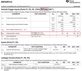
Can you please clarify the input configuration(pull up/down resistors) and leakage current of RST pin?

Regards,

Bernd

  • Hi,

    The post you linked to is for a different device (MSP430G2553). Your device has a different datasheet which you have correctly read: MSP430F2132 has an internal pullup for RST. 

    Regards,

    Evan

  • Evan,

    the post I linked and the according answer was regarding MSP430x2xx over 11 years ago. At that time G2553 was not on the market so the answer is not related to that family. As you can read G2553 came two years later with an additional question into that thread.

    Now your answer is the opposite of the answer from the linked post from over 11 years ago.

    I need a guaranteed answer to the input configuration(pull up/down resistors) and leakage current of RST pin.

    Regards,

    Bernd

  • Hi Bernd,

    What are you trying to do with this information, so that we can give the correct recommendation? We recommend always that RST pin must be connected to external 47k pull-up resistor + 2.2nF capacitor for ALL MSP430x2xx parts in our user's guide www.ti.com/lit/pdf/slau144 for correct operation, JTAG/SBW programming, and current consumption - see section 2.5 Connection of unused pins (p. 41 in current doc revision). Is there something else you need to connect on the RST pin so you are wanting to understand better the characteristics of this line, or are you not wanting to use external components here? Can you give some more context? 

    Regards,

    Katie

  • Hello Katie,

    thank you for picking this and replying fast. Here the background for the question:

    In our application we have to squeeze all lifetime out of the battery as we can. The application should operate twenty years using a 1.6Ah battery in a harsh environment.
    To do this, it is essential to know if the RST/NMI pin has a pull up/down, because it will draw current.
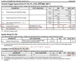
    Actually we measured no pull up/down at RST/NMI. But the datasheet is a bit unclear. On page 22 of SLAS578J these tables exist:


    So there could be a pull-up or -down on RST/NMI pin with value between 20k or 50k Ohms.
    I was not able to locate a definition of leakage current into RST/NMI. Googling the internet and searching MyTI (E2E) was not helpful.

    Again: We measured no pull-up/down on the RST/NMI pin and very low leakage. But this is not guaranteed by the datasheet ?!
    It is important to know that this characteristic will not change in future.

    Regards,
    Bernd

  • Hi Bernd,

    There is a pull-up/down resistor on the RST/NMI pin due to the nature of being a Schmitt-trigger. The default state of the RST pin being set as RST would have the resistor enabled. On our later datasheets like the MSP430F5529 we clarify these input pins more to help include the RST pin as a Schmitt trigger input. The datasheet shows the schematic of these Schmitt-trigger pins ("Port P1 Schematic" is an example).

    The leakage current characteristics are taken with the pins set as input and the resistors disabled, though I would expect the same characteristics on the RST as it is also a Schmitt-trigger input. The external 47k resistor, that Katie mentioned, is also an important aspect and if you want to use that RST pin I recommend following that.

    I think there was some confusion in the linked post as to the purpose for the 47k resistor, it isn't replacing the internal resistor but instead assisting the pull-up process.

    The datasheet lists the max you would see on those pins, which includes the RST. This does not mean that the typical current would be +-50nA.

    Regards,

    Luke

  • Hi Luke, Hi Katie,

    I am the one who asked that question originally.

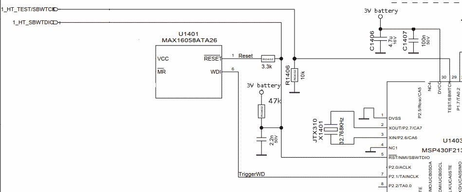
    We use MSP430F2132TRHB. The RST/NMI pin is connected via a 3.3k resistor to a WDT (MAX16058ATA26) with open collector output. With an external pull-up of 47k between RST/NMI to the battery (3Volts), the MSP starts well. If the firmware locks, the WDT asserts RST down to 220mV as wanted. Everything behaves as desired. 

    The 3.3k resistor in series between WDT-Reset and RST/NMI is needed for EndOfLine testing. We have to overide the WDT output.

    Problem: If there should be a pull up resistor inside the RST/NMI pin, the WDT might not be able to reach the required voltage level to assert a reset of the MSP430. The WDT would not be able to drive the parallel connection of the external 47k and the presumed internal 20k (minimum value in the datasheet) pull up at RST/NMI. This because of the voltage drop accross the 3.3k resistor in series between WDT output and RST/NMI pin.

    If we omit the 47k pull up resitor between RST/NMI and the battery-rail and power the whole thing up, the voltage at RST/NMI is zero and the MSP does not start.

    If we supply the 47k pull up resistor and place a DMM between RST/NMI and GND, we measure 63uA current using a 3V battery. This is exactly the current caused by 3V/47k.

    As a result of these measurements, there should be no internal pull-up resistor at the RST/NMI pin of the MSP430F2132.

    If there IS NO internal pull up at the RST/NMI pin, all is OK to us. Anyway we are affraid that suddenly that internal internal pull up resistor appears, preventing the function of the WDT.

    The circuit:

  • All,

    We are going to have to work internally to determine what the expected behavior is. I expected to have an update by next Wednesday, the 13th.

    Regards,

    Evan

  • All,

    I think the correct interpretation of the table in the datasheet is that RST shares the same pin attributes as the other ports on the device. These iocells have the option to enable a pullup or pulldown resistor. However in the case of RST this option is not available to the user, so effectively it does NOT have pullup/down functionality, nor will it ever.

    Hope that clears things up. 

    Regards,

    Evan

  • Evan,

    Sorry for digging into it like that. Thanks for the clear statement.

    Best Regards,

    Wolfgang

**Attention** This is a public forum