This thread has been locked.

If you have a related question, please click the "Ask a related question" button in the top right corner. The newly created question will be automatically linked to this question.

MSP430FR5872: Making a new board using this chip, want to make sure I have it right before production

Part Number: MSP430FR5872

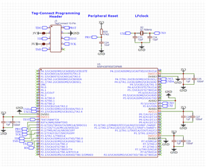
The chip will essentially act as a UART to I2C buffer. It's designed to be as low power as possible, with a supply of 3.3V. Any improvements, tips, or corrections, please let me know!

  • Hi Charles,

    All looks good except for the following:

    1. C24 (10nF).  According to the datasheet, Fig 7.3, a value of 2.2nF is the upper limit when programming the device with TI programming tools.  From experience a 1nF will work fine as well.

    2. You may have them on a different schematic page, but I don't see any pull up resistors on your I2C pins.

    Also be advised in the device errata, there is an issue USCI41 related to the UART operation.

    Now, you mention low power is important.  What low power levels are you targeting?  Reason I ask is this MSP430 can operate as low as ~1uA while running an external 32kHz crystal in low power mode LPM3 (All system clocks, except 32kHz, and CPU off).  So when not communicating I assume you want the MSP430 to consume the least amount of power, right?

    In LPM3 the MSP430's UART is not being clocked, but can automatically wake up the system clocks when the falling edge of a START bit is detected.  Once detected, the UART needs to have the system clocks running and stable before it can start properly sampling the remaining incoming data bits.  This is where it gets tricky because the system clocks can take up to 10usec to startup (see datasheet table 5.9) when coming out of LPM3.  So what this means is the UART will have to wait 10usec before it can start sampling.  At 9600 baud this delay is only  ~10% of the bit period (104us) so it shouldn't cause any issues.  But, at baud rates like 115200, where it's bit period is 8.68usec, you are likely to miss the entire START bit and cause framing errors.

    Now if by chance your baud rate is 9600, you can always use the 32kHz ACLK for the UART's clock source.  This is the only clock allowed to run while in LPM3 and there is not issue. However, if you are expected to wake up operating at a higher baud rate, you will most likely use the SMCLK and will have to use LPM0 instead of LPM3.  LPM0 will only stop the CPU but keep the SMCLK running  But this comes at a cost so to keep the current to a minimum with the SMCLK running, you want to choose the slowest possible frequency that supports your baud rate.  See section 5.6, 5.7 in the data sheet for current vs clock freq.

    Hopefully this is helpful and if you need help, let me know.

  • This is all very helpful, thank you. Thank you for mentioning pullups, though I do already have those elsewhere in my design. Good to know about the possibility of a frame error, but luckily I am indeed working at 9600baud so things should be alright.

    I'll see to reducing that cap size, and I believe that should be it. Thank you very much for your help. 

**Attention** This is a public forum