This thread has been locked.

If you have a related question, please click the "Ask a related question" button in the top right corner. The newly created question will be automatically linked to this question.

EVM430-FR6043: EVM430-FR6043

Part Number: EVM430-FR6043
Other Parts Discussed in Thread: EVM430-FR6047, , TIDA-01486

Hello,

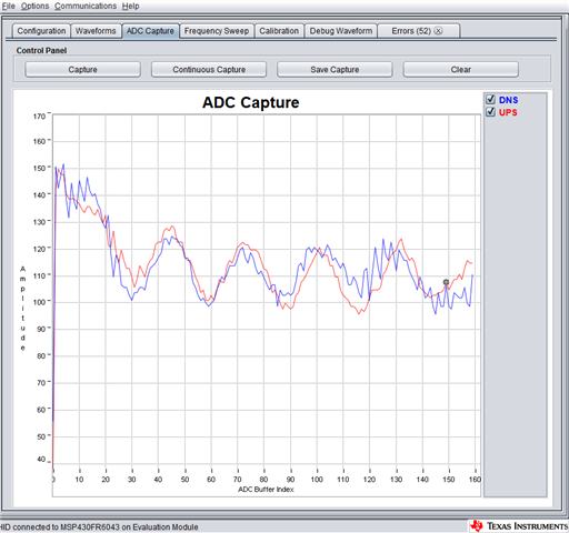
I am struggling to get good ADC capture at zero flow measurement. Our application is to do non-intrusive and non-invasive water flow measurement on metal pipe. Initially we have tried to use EVM430-FR6047 but had no success to get good ADC capture. In this forum https://e2e.ti.com/support/microcontrollers/msp-low-power-microcontrollers-group/msp430/f/msp-low-power-microcontroller-forum/818315/evm430-fr6047-ultrasonic-design-center-calibrating-clamped-on-transducers-to-work-with-metal-pipe one of you colleague recommended to use EVM430-FR6043 because of amplification feature on receiving signal but still we are not getting ADC capture.

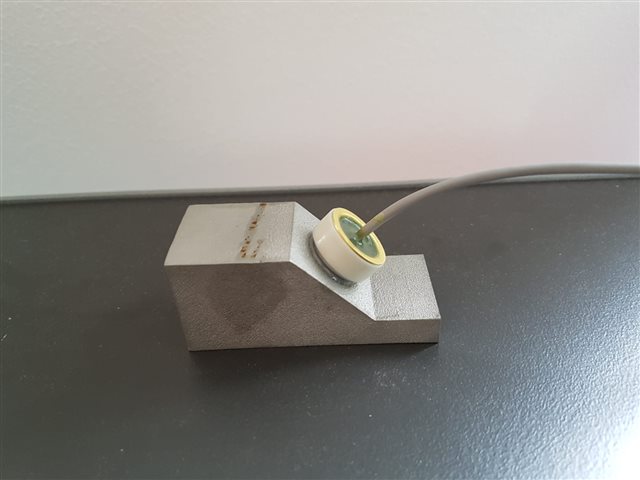
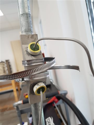
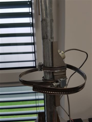
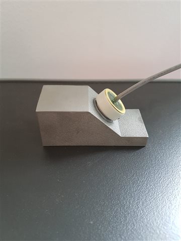
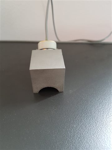
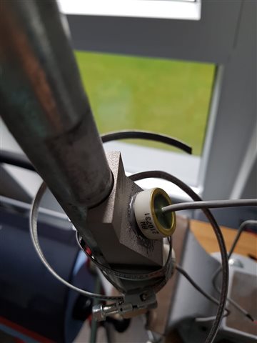
We have already modified hardware of the EVM to do flow measurement, 1MHz piezo transducer is glued with 3D printed coupler which is attached one the pipe. We have installed piezo next to each other and sound wave travel in a V-shape into the metal pipe. Pipe is full of water without any air bubble.

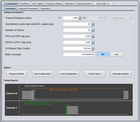
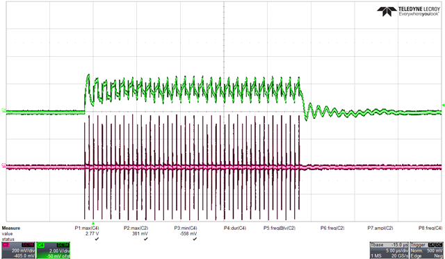
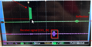
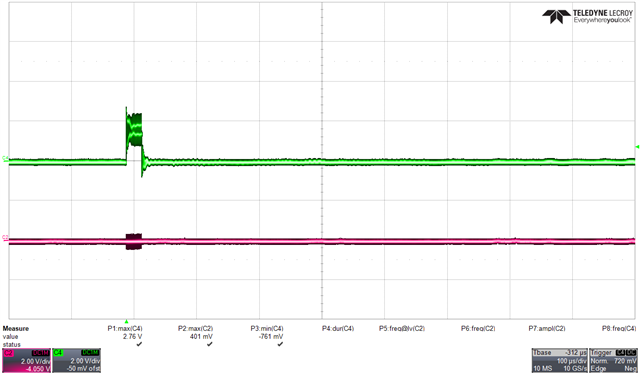
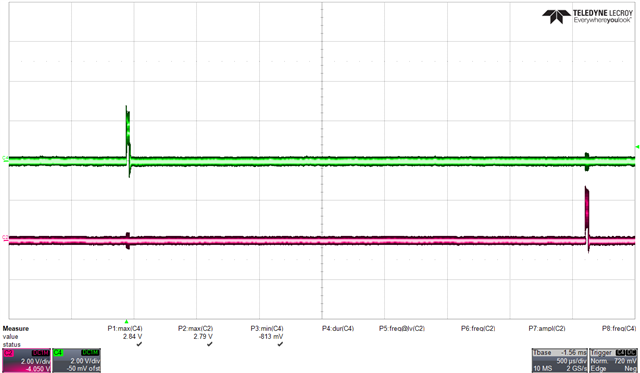
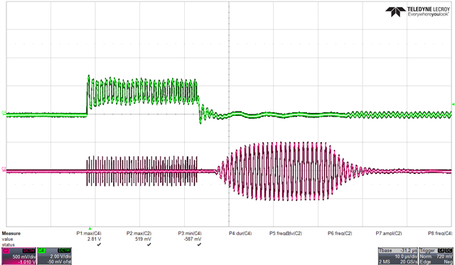
As I can see TX pulses train on oscilloscope but due to very low signal can not see receiving signal. According to you colleague, EVM430-FR6043 has an amplification feature, could you please let us know is there any way to increase the receiving signal via GUI? 

Have you done flow measurement on metal pipe? 

  • Hi Bilal Ahmed Siddiqui,

    Clamp-on flow measurements on metal pipes has not been extensively investigated by TI. As noted in the post you linked, you will need some external amplification. 

    A couple things to consider:

    1. The FR6043 EVM's external RX amplifier has a bandwidth of 584kHz. This may be hurting you since you are using 1MHz transducers. 
    2. TI offers https://www.ti.com/tool/TIDA-01486 for boosting TX and RX signal as a reference design only. This may be applicable for your design.

    Can you share a scope captures of TX and RX? Can you share a picture of your 3D printed pipe fixture?

    Regards,

    Evan

  • Hi Evan,

    Thank you for your support.

    Could you please tell me, is it somehow we can buy evaluation board of TIDA-01486 for testing and performance evaluation?

    Below you can see the ADC capture, parameters, Oscilloscope waveform and our 3D fixture:


  • Hi,

    Thanks for sharing detailed photos of your setup. 

    Could you please tell me, is it somehow we can buy evaluation board of TIDA-01486 for testing and performance evaluation?

    This board is available for reference only. It cannot be purchased.

    Can you use your scope to capture more of the RX signal? Currently your capture only shows the TX signal (green). The RX signal shown (pink) is purely cross-talk. The true RX signal will appear later in time after it as traveled through the media. An example of an RX signal (boxed in red):

    Once you are able to see the RX signal I would recommend making small adjustments to the physical location of one of the transducers to see if you can improve the RX signal strength. 

    A couple questions for you:

    • How did you pick the "V" shaped configuration for the transducers?
    • What material is between the transducer face and pipe? Air (or the air in 3d prints) will have a significant attenuation affect 

    Regards,

    Evan

  • Hi Evan,

    Thank you again for your feedback.

    I have adjusted my scope and I did not see any RX signal as in your image RX signal in pink color , you can see in below images:


    To be sure transducer and EVM works fine, I took a bowl full of water and put both piezo in front of each other in the bowl. Getting really great RX signal as per expectation. Here is the image:

    It seems like metal pipe has alot of attenuation therefore RX signal can not appear.

    Regarding you question:

    Q1: Both the transducer are attached on metal 45° 3D printed fixture in a series. Once piezo 1 send pulses it will penetrates into the pipe, hit the wall of the pipe and reflect back to piezo 2 in a V shape configuration. Of-course there are some losses due to refraction but at least piezo 2 will get some waves after reflection.

    Q2: Transducer connected with the metal 3D fixture by using a glue (2-component epoxy metal glue). There is nothing in between 3D fixture and face of the pipe, only air exist. We have tried to put normal gel in between fixture and pipe but still did not get TX signal.


  • I have couple of more question,

    Q1: Reference design TIDA-01486 capable to connect 2 pairs of PZT. We want to connect only one pair of PZT, should we modify the reference design or can we use same as it is?

    Q2: Using TIDA-01486 with EVM430-FR6047/43, should we need to modify GUI software? 

  • Thanks for sharing the scope captures. 

    Yes, it seems like there is too much attenuation though the 3D fixture and pipe. 

    Have you tried making small adjustments to the physical positioning of the transducers? There may be refraction at the interface boundaries that may shift the ideal placement of the transducers away from the theoretical best position.

    You might also try mounting the transducers on opposite sides of the pip to see if you can get a clearer signal.

    Regards,

    Evan

  • I have also tried to displace the transducer and I also tried to put the transducer in opposite sides of the pipe but still have the same problem. Either way I can not see RX signal. Could you recommend me any solution? would it be helpful to design amplification board same as it reference design of TIDA-01486 to get RX signal?  

  • Either way I can not see RX signal.

    Are you observing the RX signal on the scope or GUI?

    would it be helpful to design amplification board same as it reference design of TIDA-01486 to get RX signal

    Yes, based on the fact that you aren't able to see any RX signal I would recommend some amplification. Metal pipes are notoriously for signal attenuation.

    Q1: Reference design TIDA-01486 capable to connect 2 pairs of PZT. We want to connect only one pair of PZT, should we modify the reference design or can we use same as it is?

    You can modify it to use 2 channels instead of 4.

    Q2: Using TIDA-01486 with EVM430-FR6047/43, should we need to modify GUI software? 

    I don't believe any software modifications should be necessary.

  • We are observing the RX signal both on Scope and GUI. In both cases, we could not able to get RX signal. Could you suggest me how could we get the RX signal on metal pipe?

  • If we are going to design amplification board using TIDA-01486 reference design, what modification should I expect to have for 1 pair of transducers? as per my understanding we should not use MUX (TS5A3357DCUR) right?

    Could you please also explain briefly, how could I connect CHxOut and CHxIn with EVM 6047 on J8 as I can see on J8 only 2 pins are CHxOut pins and rest of the pins are ground?

  • We are observing the RX signal both on Scope and GUI. In both cases, we could not able to get RX signal. Could you suggest me how could we get the RX signal on metal pipe?

    Metal pipes are bad for signal attenuation. Mechanical design is important, but unfortunately this is not TI's expertise. The only other option is to increase TX signal strength and RX signal gain. 

    Let me work internally to figure out the best way to connect this reference design with the EVM430FR6047.

  • Hi,

    Just a quick update: I'm still working to figure out the best way to connect the EVM and the amp circuit.

    Question: do you have access to a EVM430-FR6043?

    Regards,

    Evan

  • yes I have an access to EVM430-FR6043 and we already figured it out how to connect EVM with amplification circuit. I am just thinking about what would be the alternate solution if amplification circuit would not be sufficient to get the RX signal.

  • yes I have an access to EVM430-FR6043 and we already figured it out how to connect EVM with amplification circuit

    Ok great!

    I am just thinking about what would be the alternate solution if amplification circuit would not be sufficient to get the RX signal.

    Understood. If you aren't able to get enough signal with an external amplifier you will likely need to adjust the mechanical design. You might try different transducers with different frequencies, different attachment methods, or different transducer placement. But TI doesn't have expertise in this area.

    Regards,

    Evan

  • one question: according to the datasheet MSP430-FR6043 can bear maximum 1.65V on CHx_IN pin. How could it be possible to amplifying the signal in terms of Voltage? our application is to amplifying up to 18V, this voltage could damage MSP430-FR6043.

  • In this link https://e2e.ti.com/support/microcontrollers/msp-low-power-microcontrollers-group/msp430/f/msp-low-power-microcontroller-forum/1111257/msp430fr6047-external-amplifier-to-increase-the-drive-voltage-and-amplify-received-signal/4119095?tisearch=e2e-sitesearch&keymatch=EVM430-FR6047%2525252520metal%2525252520pipe#4119095 you are explaining TIDA-01486 has an analog switch/mux to protect the MSP430 inputs. As we are using only 1 pair of transducer, one of your colleague recommend not to use analog switch/mux while using 1 pair of transducer in this link e2e.ti.com/.../3383916

    Could you please explain how analog switch protecting MSP430 inputs? 

  • Hi,

    The abs max voltage on USS CHxIN is 1.65V. However the protection circuit on the output of the RX amplifier will only clamp the voltage between 0 and ~3.5V based on the diode selection. As an example, if a transducer is driven, the RX is also driven directly (see diagram below). This will likely result in a large signal at the output of the RX amplifier. The switch protects the device from seeing this.

    Regards,

    Evan

  • Could you please again explain briefly, how these three diodes on the RX side protects the MSP430 chip and what is the role of Schottky diode in this case?

  • We have figured out how these three diodes protect the MSP430 and role of Schottky diode.

    I have other question, as we are using only 2 piezo transducer and reference design made up for 4 channels. Could you provide us 2 channel software may be header files or so on?

  • The default configuration (which the current software supports) works with 2 channels. I'm not aware of anything that would require different SW.

**Attention** This is a public forum