This thread has been locked.

If you have a related question, please click the "Ask a related question" button in the top right corner. The newly created question will be automatically linked to this question.

MSP-FET: Would like to pass a hex file that includes boot and app

Genius 15759 points
Part Number: MSP-FET
Other Parts Discussed in Thread: MSP430F5335, UNIFLASH, MSP430F6638, MSP430G2230

Hi Experts,

Seeking your assistance on this query from Cx:

"I have a MSP-FET Flash emulation tool and would like to program my circuit board.
I have a board that uses the MSP430F5335
I have a JTAG port to use.
I would like to pass a hex file that includes boot and app.

My development team has been using the older MSP-FET430UIF with FETPro430 Lite from elptronics for years, but I'm struggling to get this MSP-FET device to work."

Thank you.

Regards,
Archie A.

  • Hi Archie,

    Can you describe more the issues that they are having?

    1. Do they need assistance hooking up all the wires?
    2. Are they getting error codes?
    3. Do they want to know what program to use to flash the device?

    Regards,

    Luke

  • Hello Luke,

    Good day. Cx responded:

    I’ve been using FETPro430 Lite to flash my device with an older white MSPFET tool, now I’m using the black one and it gets stuck at “ERASE FLASH”. At the moment, I only need to flash the hex file, I don’t need to debug.

    For your assistance. Thank you.

    Regards,
    Archie A.

  • Hi Archie,

    With the black MSP-FET they should be able to use Uniflash to flash a hex file. Make sure to connect the appropriate wires, there is a quick start guide on Uniflash that can assist as well.

    Regards,

    Luke

  • Hello Luke,

    I still cannot program a MSP430F5335 or MSP430F6638.  Again, I’m have a hex file that includes both the boot and the app. I have been able to program a MSP430G2230 with an app only hex.

    Does my programmer need to be updated?  How do I do that?

    Regards,
    Archie A.

  • Hello Archie,

    Luke is out today, so I'm helping out.  What does the customer mean by Boot and app?  The MSP430F5335 has a BSL provided, but that is stored in ROM, and is not able to be updated.  Do they have a custom BSL stored in flash?  

    Anyway, the MSP-FET should automatically be updated if you try and download a project through Uniflash or Code Composer Studio.  https://www.ti.com/tool/UNIFLASH   Please download this software and just try programming an image that way.  When attempting to download, the first step will be for the software to check the MSP-FET firmware and update if necessary.  

    I checked and the FET430pro Lite should support the MSP-FET (and it seems like it's mostly working.)  If these update steps don't work or you try them and there are no updates initiated, let use know and we can try to reach out to elprotronic to see if they can comment.  

    Thanks,

    JD

  • Hi JD and Luke,

    Thanks for the inputs.

    I am still coordinating this query with the customer, and they are in the process of testing the programming. In the meantime, saring you here the updates they shared:

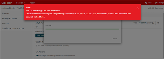
    I tried using uniflash this morning. It properly detected my processor, MSP430F5335. When I try to verify my hex file, I get this error message. In case there was an issue with the file name or location, I moved the file to the root directory C:\ and renamed it UVC238.hex. I received the same error. I should have access to a different programmer in a few days and can try it again.

    Thank you.

    Regards,
    Archie A.

  • Hi Archie,

    For the "a data verification error occurred, file load failed" error there are many possible reasons.

    Here is a CCS write up that might assist in finding the root cause Troubleshooting Data Verification Errors, though this is for CCS the same applies to Uniflash.

    Are they wanting to verify that the program is the same as what is programmed or did they want to load the program into the device?

    Regards,

    Luke

  • Hello Luke,

    Good day. Cx responded:

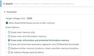
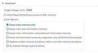
    Thanks for the write up, but I’m not sure it’s applicable.  Maybe it is and I don’t understand. Today I was able to use the old “white” MSP-FET430UIF debug tool to successfully program my board using UniFlash.  The following settings were required: 

    When I use the new “black” MSP-FET Flash Emulation Tool it starts the process but then generates the following error:

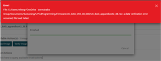
    And

    Any new suggestions based on this testing?  I don’t think buying obsolete programmers from ebay should be my best solution.

    Thank you for your continued support,

    Archie A.

  • Hi Archie,

    I agree that the new MSP-FET should work if the old version does too. Have they been able to successfully program with that MSP-FET in other applications? Do they know if the MSP-FET firmware has been updated to the latest version?

    Regards,

    Luke

  • Hello Luke,

    Thanks for responding.

    I don’t think that it has been updated. FETPRO430 Lite shows that there is a newer version, but after completing the process, the version number hasn’t changed. I was under the impression that UniFlash will automatically check the version and recommend an update, but it did not.

    For further assistance.

    Regards,
    Archie A.

  • Hi Archie,

    Let's try to take a different approach here. Try programming using the gpio_toggle example, the simple program will help us isolate to debug the MSP-FET.

    Regards,

    Luke

  • Hello Luke,

    Cx ready to give this a try, but not a developer. Customer would like to know how to get from this program to a hex file they can flash.

    Any guidance? Thank you.

    Regards,
    Archie A.

  • Hi Archie,

    I've attached TI-txt hex versions for both the MSP430F5335 and the MSP430F6638

    MSP430F5335_1.c.txt
    @8000
    81 00 00 64 B1 13 30 00 0C 43 B1 13 00 00 1C 43 
    B1 13 2A 00 32 D0 10 00 FD 3F 03 43 
    @ffca
    14 80 14 80 14 80 14 80 
    @ffd4
    14 80 
    @ffd8
    14 80 14 80 14 80 14 80 14 80 14 80 14 80 14 80 
    14 80 14 80 14 80 14 80 14 80 14 80 14 80 14 80 
    14 80 14 80 14 80 00 80 F1 03 B2 40 80 5A 5C 01 
    D2 D3 04 02 D2 E3 02 02 B1 40 20 4E 00 00 81 93 
    00 00 F8 27 91 83 00 00 81 93 00 00 F3 27 FA 3F 
    03 43 03 43 FF 3F 03 43 1C 43 10 01 
    q
    

    MSP430F66xx_1.c.txt
    @8000
    81 00 00 64 B1 13 30 00 0C 43 B1 13 00 00 1C 43 
    B1 13 2A 00 32 D0 10 00 FD 3F 03 43 
    @ffca
    14 80 14 80 14 80 14 80 14 80 14 80 14 80 14 80 
    14 80 14 80 14 80 14 80 14 80 14 80 14 80 14 80 
    14 80 14 80 14 80 14 80 14 80 14 80 14 80 14 80 
    14 80 14 80 00 80 F1 03 B2 40 80 5A 5C 01 D2 D3 
    04 02 D2 E3 02 02 B1 40 20 4E 00 00 81 93 00 00 
    F8 27 91 83 00 00 81 93 00 00 F3 27 FA 3F 03 43 
    03 43 FF 3F 03 43 1C 43 10 01 
    q
    

    If they have CCS here are the steps I took to convert to get a hex file.

    Right click on the project -> Properties -> Build -> MSP430 Hex Utility 

    Enable 'MSP Hex Utility'

    ->Output Format Options

    Output format TI-TXT hex (--ti_txt)

    Then build the project and go into the debug folder, the .txt file will be your TI-TXT hex file.

    Regards,

    Luke

  • Hello Luke,

    Customer responded:

    I was able to program MSP430F5335_1.c.txt .
    I then tried to program my hex file and it continues to fail.  When I switch to the old MSP-FET430UIF device, it works as expected.  I’ve attached my process. 

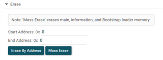
    Please note that part of the setup is to change the Erase setting to

    I do not recall what the original values were.  I tried once more to program with MSP430F5335_1.c.txt and it failed.  I think because of this setting.  Can you send me the default values?  I removed and reinstalled UniFlash to try and recover them, but they remained 0 and 0. Please send me the default values.

    Regards,
    Archie A.

  • Hi Archie,

    The default values are Start Address: 0x0 and End Address: 0x0. This is for the Erase by Address function, so if they wanted to program to a specific section in memory they could erase only that sector. The normal use is to erase the main memory only which is the top section.

    If they wanted to use the address part then they need to select "By Address Range".

    Did they try to set it to By Address Range the second time they attempted to program?

    Make sure they are selecting "Load Image" under the program and not the "Verify Image".

    Regards,

    Luke

**Attention** This is a public forum