This thread has been locked.

If you have a related question, please click the "Ask a related question" button in the top right corner. The newly created question will be automatically linked to this question.

EVM430-FR6043: Gas flow meter calibration & measurement rate

Part Number: EVM430-FR6043

Hello,

I am trying to use flow + temperature calibration and have 10ms or less UPS0 to UPS1 Gap for the gas flow meter using EVM430-FR6043 and Ultrasonic Sensing Design Center. How can I change the USSSWLib_template_example source code to achieve these? 

Additionally, I am having a hard time understanding what ADC Sampling Frequency and Signal Sampling Frequency are. What are their differences? On the GUI, modifying ADC Sampling Frequency is disabled. Is there any way to access this value and change it?

Thanks.

Min

  • Hi Min,

    For your first question, it looks like this value in the GUI corresponds to the #define USS_SYS_MEASUREMENT_PERIOD in the template example. If you navigate to USS_userConfig.h you can redefine it. As you can see in the comments, this value is the number of LFXT cycles, so to reduce the UPS0 to UPS1 gap below 10ms, you'd need to set this value below 328. You can find the formula by which the USS GUI determines this value at this link.

    As for the difference between the ADC sampling frequency and the signal sampling frequency; these two are related to each other and are determined (in the USS GUI) using two other parameters: the ADC oversampling rate and the PLL frequency. You can find this relationship in table 11.12 in the ultrasonic design center user guide. The GUI will not allow you to change signal frequency, ADC oversampling rate, and ADC frequency independently of each other because some settings can result in invalid PLL settings. If you plan to try to change these settings on your own in the USS template example, you must make sure that your final configuration results in a valid PLL configuration.

    Keep in mind that you can also just make these changes using the USS GUI, and export the header to your template project using the "generate header" button in the GUI. This seems like the easiest way to go and the least likely to lead to other issues so I'd like to encourage you to go that route.

    Let me know if that answers your questions,

    Dylan

  • Hello Dylan,

    Thank you for your response. Your advice helped me a lot. However, I have some follow-up questions. 

    You mentioned that the ADC sampling frequency, the signal sampling frequency, the ADC oversampling rate, and the PLL frequency are related to each other. From the link you provided, I assume that the PLL frequency is the signal sampling frequency multiplied by the ADC oversampling rate. Would it be okay to set the signal sampling frequency and ADC oversampling rate to any values as long as Signal Sampling Frequency * ADC over Sampling Rate / 1000 equals the value for the PLL frequency (80 in the default case)? 

    I am not able to change the ADC sampling frequency value through GUI. Will I be able to modify it through template example code? What constraints are there when changing this parameter?

    Lastly, is there a way to access the Flow+Temperature Calibration feature? If I have a set of data for the calibration, how can I implement it in the code so the calibration result is applied to waveform values outputted by GUI?

    Thanks,

    Min

  • For your first question: Yes, I believe that you can adjust these parameters as you wish as long as the result equals PLL frequency.

    To the second question: This would normally be done on the FR6043 device by adjusting ADC12SSEL and ADC12DIV, which are parameters for the ADC12CLK. However, the designers of the GUI prevent the user from changing this value for a reason, and I think that changing them is likely to cause many unforeseen issues. I am currently looking further into the details of this but I'd really like to encourage you to utilize the values that the GUI allows. 

    As for using calibration data, it looks like all of this data is found/adjusted in the USS_Config folder. Did you collect this data using the GUI?

    Could you please explain why you need to adjust all of these things in the code rather than using the GUI and letting it generate these values? The GUI is optimized to work with the EVM you are using.

  • Hello Dylan,

    Regarding the ADC frequency, I wanted to adjust the value to decrease the sample number that the application is processing. As I previously mentioned, my goal is 10ms or less UPS0 to UPS1 Gap, in other words, 100Hz or higher measurement rate. When I tried changing various parameters with 10~20ms UPS0 to UPS1 Gap, I got "time between measurements is greater than ups0 to ups1 gap" errors, so I would like to find a solution. Are there other methods to avoid this issue without changing ADC frequency and increasing UPS0 to UPS1 Gap?

    For the calibration, I wanted to have my calibration data because, probably due to the characteristics of the tube and the transducer that I am using, the value output by GUI deviates at different flow rates, and I thought calibration data would help compensate for that. Also, since I wanted to use the gas flow meter in various environmental settings, I thought integrating the temperature factor into the calibration would help. Is the data "USS_TEMPERATURE_LUT_VALUES" what you are referring to? The first column is the sound velocity calculated based on temperature, the second is the temperature, and what is the third column? Can I substitute these values with the calibration data collected with the EVM board?

    Thank you.

    Min

  • Min,

    I see what you are saying. 

    Have you tried adjusting the USS_SYS_MEASUREMENT_PERIOD define / the value assigned to ussSystemConfig.measurementPeriod? After doing this are you still getting that same error? What exactly are you setting your UPS0 to UPS1 gap to, and what are you setting your UPS and DNS gap to?

    Also, I can see in our design guide that the two files that hold the calibration data are "USS_meterVFRCalibFLowTemperature.h and "USS_temperatureLUT.h". So you should be placing the calibration data that you already have into these files as well. 

    As for explanation of the columns in the look up table, I found this explanation in USS_temperatureLUT.h:

    The format of the LUT is sound velocity (c) , temperature (t), and slope between the k and k+1 element = temperature resolution / (c(k+1) - c(k)). The water sound velocity equation used (Bilaniuk and Wong 148 pt equation):
    c = 1.40238744*10^3 + 5.03836171*t - 5.81172916 * 10^-2* t.^2 + 3.34638117 * 10^-4 *(t.^3) - 1.48259672 * 10^-6 *(t.^4) + 3.16585020 * 10^-9 * (t.^5)

    There is a reference link in that file as well but it is no longer available. I've found another one here

    I am going to continue to look into the error message you are getting to see if I can find a sure-fix for this. Thank you for your patience on this. As always, let me know if you have further questions.

  • Hello Dylan,

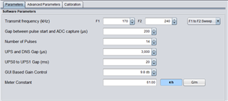
    The following images are captures of the parameters configuration that I am using.


    In addition to these parameters, I am testing using USS_SYS_MEASUREMENT_PERIOD = 655 (20ms) and USS_SYS_MEASUREMENT_PERIOD = 328 (10ms). I don't have much of a problem when using 20ms, but I am observing "time between measurements is greater than ups0 to ups1 gap" errors when using 10ms.

    I am using MSP430FR6043EVM_USS_Gas_Demo, but I cannot find USS_meterVFRCalibFLowTemperature.h file. I assumed USS_meterVFRCalibFLowTemperature.h is for flow + temperature calibration, so, ultimately, I would like to use this to update the calibration data to account for flow rate changes at different gas temperatures. Given that, I found USS_meterVFRCalibFLowTemperature.h in the water flow meter example, and the data points have the following format: "

    .iq16Flow = _IQ16(6.515878/USS_VFR_LARGE_PIPE_ADDL_SF),                \
            .iq16Temp = _IQ16(44.20),          "
    I am assuming 6.515878 is VFR collected by flowmeter using MSP430, and 44.20 is the temperature in Celsius. Then what is USS_VFR_LARGE_PIPE_ADDL_SF, and how should I set it?
    The current application that I am using is utilizing USS_temperatureLUT.h, and, as you mentioned, it follows three column format: sound velocity (c), temperature (t), and slope between the k and k+1 element = temperature resolution / (c(k+1) - c(k)). I understood how sound velocity and temperature are calculated/measured. However, I am confused about how the "slope between the k and k+1 element = temperature resolution / (c(k+1) - c(k))" is acquired. Given that I know the input flow rate and have VFR measurement by MSP430 gas flowmeter, how should I process the data to get the "slope between the k and k+1 element = temperature resolution / (c(k+1) - c(k))"?
    Thanks,
    Min
  • Hi Min,

    I am working with another member of the team to help address your problem. Expect an update from me tomorrow afternoon.

    Thank you for your patience.

  • Min,

    After discussing with our USS expert I have a few notes:


    1) For gas metering applications, we recommend a UPS0 to UPS1 gap of 50ms. The UPS0 to UPS1 gap is the time between measurements. What I mean by this is that when you get the "time between measurements is greater than ups0 to ups1 gap" error, it means that the actual time that the measurement is taking is longer than the gap you specified in your settings. You can speed up the measurement by reducing the UPS to DNS gap, but due to transducer ringing and reflections, you can only reduce this by so much before you start running into issues. I see you said that you have successfully set the UPS0 to UPS1 gap to 20ms; I believe the best thing for you to do is trial and error to see how short you can make this gap without getting the errors. 20 ms may be the lowest you can go.

    2) The USS_VFR_LARGE_PIPE_ADDL_SF define is basically just an extension of volume scale factor. If you have the volume scale factor set to the maximum and need to increase it further, you do so by scaling up the USS_VFR_LARGE_PIPE_ADDL_SF. It is used as follows:

    Volume flow rate = (volume scale factor * additional volume scale factor) * dTOF / (absTOFUPS * absTOFDNS)

    3) The slope is found as shown in the image below:

    To calculate the sound velocity divide the length between transducers by absTOF. Then using temperature data, the equation may be evaluated to find the slope/ the third element in the table.

    Let me know if this clears things up for you.

  • Hello Dylan, 

    1) I understand that there are some constraints when designing a gas flow meter using MSP430. If I were to do trial and error, I would first need to optimize the parameters and system to acquire the minimum UPS0 to UPS1 gap. If so, what are the things that I would need to do for the optimization? What parameters/configurations should I adjust on GUI and the source code to reduce the UPS0 to UPS1 gap as much as possible? Would improving the CPU by increasing the main clock help reduce the measurement time? Are there any hardware optimizations that I could try?

    Currently, the clock is initialized through hal_system_Init() function for the demo application. In this case, what main clock frequency is the MSP430 using? Is it the same frequency as HSPLL = 80MHz? If I change the main clock frequency, will it affect the HSPLL frequency used for USS as well?

    Also, when we previously discussed about adjustment of the signal sampling frequency and ADC oversampling rate and that I have to set them so they satisfy the condition in which Signal Sampling Frequency * ADC over Sampling Rate / 1000 equals the value for the PLL frequency. If I were to change PLL frequency, I am assuming that I would need to adjust the signal sampling frequency and ADC oversampling rate accordingly, is this correct? In that case, is it possible to change the rate so Signal Sampling Frequency * ADC over Sampling Rate / 1000 equals to a divisor of the PLL frequency? For example, if I have the PLL frequency of 80 MHz, can I have the signal sampling frequency of 500kHz with the ADC oversampling rate of 80 or the signal sampling frequency of 1MHz with the ADC oversampling rate of 40? Will this help reducing the data size thus reduce the measurement time?

    2) From your response, I am assuming the USS_VFR_LARGE_PIPE_ADDL_SF is the value that I would need to acquire using the acquired data. Then if I edit the source code to utilize and have my own sets of data for the USS_calibrateVFRFlowTemperature function provided by the USS library, will I be able to use the flow + temperature calibration feature on the evm430 FR6043 gas flow application?

    3) Your answer clarified the question that I had and I do not have further question regarding this matter.

    4) I also have additional question regarding the detection of the max correlation index point. I was regarding through the technical references by TI and I understand how TI finds the max correlation index point to calculate the delta ToF. However, given that the max correlation value is limited to 1, it's possible that max correlation occurs at multiple points within the range of the index point. In this case, how does the code determines which index represents the "correct" the delta ToF? I am detecting some spikes in the delta ToF waveform which I think is caused by detecting wrong max correlation point. Is there a way to fix this problem?

    Thank you for the help.

    Sincerely,

    Min

  • 1) Software optimization guidelines can be found in this USS for gas metering reference design in section 3.2.1.5. Some notes on hardware optimization can be found in section 2 of the gas meter design guide. Generally speaking, the first thing I'd look to do is lower the UPS to DNS gap. However, this can eventually lead to issues with the reflection of the UPS signal interfering with the DNS signal, so you will have to be careful with this. You could also try reducing the number of pulses, although this likely won't lead to a huge increase in speed. I do not believe that increasing CPU main clock would be the way to go here as the data processing is done by the low energy accelerator. 

    The CPU clock and HSPLL clock are separate. The max clock frequency for this device in active mode is 16MHz. Changing the CPU clock frequency won't change the HSPLL frequency unless you also change the HSPLL configuration or input.

    What you are saying in the last paragraph should generally help reduce processing time by reducing the amount of data. However, in our reference design guide above we recommend a signal sampling frequency of at least 3.4x the transducer frequency, so keep this in mind when adjusting your parameters. I'd recommend that you just try using these adjustments to your settings to see what you get. Remember that reducing the amount of data you are collecting is also going to affect the accuracy of your final measurements. 

    2) This define is just used to scale up your volume scale factor in case the limit imposed by the iq21 format prevents you from utilizing the correct value. So this would be determined using the same acquired data that you obtained when you got the volume scale factor in the first place. If you were able to utilize the correct volume scale factor already, then you can leave the value of USS_VFR_LARGE_PIPE_ADDL_SF as 1.

    4) I am consulting with our expert on this one and will provide an update later but for now, I will say that this algorithm has been working in production for the lifetime of the product and that I do not believe that the correlation algorithm is leading to dToF spikes. This could be caused by a number of things, especially considering that your set-up is using very tight timing bordering on causing errors anyway. I will update you later when I have more information on this.

  • Closing this thread as its original questions have been resolved and further discussion has continued offline.

**Attention** This is a public forum