This thread has been locked.
If you have a related question, please click the "Ask a related question" button in the top right corner. The newly created question will be automatically linked to this question.
These are the accuracy values after phase calibration. Calibrated at 240V, 10A and 60 degree leading phase angle. And the accuracy for current varying from 1 to 100, the 
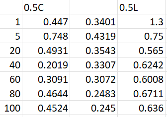
results are in the below attached image for 0.5 leading, unity pf and 0.5 lagging.
Hi Antony,
Can you give me more information?
Regards,
Luke
Yes we are using your EVM.
Leftmost column is for Current in ampere.
And the rest of the columns are % error in active power readings from the Energymeter for 60 deg leading, unity and 60 deg lagging power factors.
Hi Antony,
Can you send a screenshot of the Phase Results given from the calibration?
Looking at both our Single Phase and 3-Phase metering implementations the calibration results achieved are much better. Considering you linked a different MCU did you make any adjustments to the EVM?
Regards,
Luke
Hi Luke,
I am attaching below the schematics of the energy meter system we have developed. ARKA_GW_CARD_2P6-R3 Schematic (2).pdf
We have mostly followed the reference design provided by Ti and made only minor changes to it. We are using and Raspberry Pi to serially communicate with the MSP430F6749A IC and read, calibrate data. This https://software-dl.ti.com/msp430/msp430_public_sw/mcu/msp430/EnergyMeasurementDesignCenter/1_40_00_03/release/EnergyMeasurementDesignCenter_1_40_00_03/docs/users_guide/html/Energy_Measurement_Technology_Guide_html/markdown/ch_comm_protocol.html guidelines were followed for Gain and Phase calibration.
Hi Antony,
Looking at the Current and Voltage circuits there is nothing obvious that I see. From the information in our design guides, I would expect some accuracy differences based on the type of current sensor you utilize. Are you using Current Transformers or Shunt based for your current sensor?
Regards,
Luke
Hi Luke,
We are using Current Transformers for sensting. We tried 1000:1 ratio and 2000:1 ratio CTs of different current ratings for sensing. (It will be helpful if you can recommend a specific CT for better accuracy as well as any hardware changes or any specific resistors that should be modified for better accuracy)
With these CTs we were able to bring the % in error for unity p.f up to 0.05% when we calibrated at 240V, 10A unity p.f but at 60degree lagging and 60degree leading the error was up to 2% to 3% which was very high so we started calibrating at 240V 10A 60 degrees lagging p.f which gave error as low as 0.3% to 0.2% for unity p.f which was very high when compared to the calibration at unity p.f but gave an almost identical % in error for all 3 phase shifts as shown in the 1st post in this thread. We are almost on the brink of getting the desired 0.5% error for all 3 phase shifts. Can you recommend any changes that might give better accuracy and any relevant documents for better phase calibration other than what Energy measurement design center document provides?
Hi Antony,
I'll get back to you on recommendations for the CTs, on our EVM we used custom CTs but we also measured with high-end CT on later on the documentation. Depending on your CT accuracy results or passive component selection would change as well.
Regards,
Luke
Hi Antony,
Can I have some more information from your testing.
Regards,
Luke
**Attention** This is a public forum