Because of the holidays, TI E2E™ design support forum responses will be delayed from Dec. 25 through Jan. 2. Thank you for your patience.

This thread has been locked.

If you have a related question, please click the "Ask a related question" button in the top right corner. The newly created question will be automatically linked to this question.

MSP430FR6047: USS water flow questions

Part Number: MSP430FR6047

Hello,

I am trying to built a water meter sensor using the using MSP30FR6047EVM rev 2 and a DN25 pipe in which the distance of the transducers is about 80mm and I have some questions.

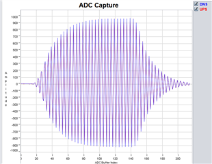
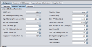
1. Are the below settings and adc capture good? Do I need to make any changes?

2. After I finish with the configuration of the evm, I will pass the configuration settings into a custom MSP30FR6047 board which has the same pipe and transduser distance. Except of the meter constant and the meter calibration parameters, is there anything else that needs to be changed?

  • Hi Panagiotas,

    1. Your ADC capture looks quite good. All of the settings in your screenshot look good as well. As long as you have verified that the waveform window (dToF, aToF, VFR) are accurate to the actual values in your test environment, I'd say those look good as well (it looks like this is captured with zero or near zero flow?).

    2. No I believe that once you've changed your meter constant and calibration parameters you should be good to go.

  • It is captured with zero flow. How can I calculate dToF and aToF in my enviroment? Also sometimes the ADC count has a +/- 100 fluctuation, is this a problem? How can I make the VFR better as it is almost always under 0 value when it should be there?

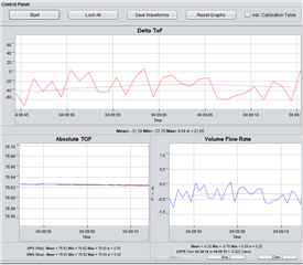
  • If you know your flow is zero, then observe that your data in the waveforms tab shows a very low differential time of flight (it does) and that your absolute times of flight are very close and constant (they are), that verifies that your time of flight data is accurate.

    The device calculates dToF and aToF. You can calculate aToF by finding the flight path of the signal and dividing it by the speed of the ultrasonic wave in water (should be around 1500m/s). This can be used to verify the value that the GUI shows. If you know the flow rate is zero then the dToF should theoretically be zero as well. The value in your image is nearly zero plus some insignificant noise so it looks good.

    Could you take a screenshot or two demonstrating the ADC count fluctuation you're seeing and post it here? Based on your short description I am not able to tell if this is an issue so some additional description would help.

    The VFR shown is extremely low. It is going to be hard to get it much closer to zero. Generally speaking, reducing noise in the environment, making sure that your test set up actually has zero flow, checking the accuracy of your transducers, and careful configuration can increase accuracy. The exact set up of your test environment (pipe material, transducer arrangement) can also affect your data. On our product page you can find some documents on transducer selection and hardware setup. However I think you will find it hard to make a significant increase in accuracy. Your readings all look good in your screenshots.

  • Here is a second adc capture where the amplitude is lower (I mistakenly wore ADC count, I don't know if they are the same)

    Also I changed the Delta TOF Offset to 5. Which one do you think is better to keep? 0 or 5?

  • Panagiotis,

    Your ADC capture still looks good. The amplitude is certainly a little lower than in your other screenshot but it still looks good and within the acceptable range of values. As long as you aren't seeing any other issues with your readings I think this is OK. 

    I think the change you made to the dToF offset is good, as it seems to center the signal around 0 liters per hour. I would say you should keep it.

  • Great, that's good to hear.

    I have a few more questions. 

    In what unit is algRes->volumeFlowRate and what is the difference with this formula: return (float)( ( (float)g_ResultsOfLastMeasurement.last_FlowRate *
    (float)rate )/ ( (float) MILLISECONDS_IN_HOUR) );?

    In which variable is the meter constant used? volumeFlowRate or volumeFlowRateNoCalib?

    Does the problem referenced here still exist? MSP430FR6047: EVM430-6047 Volume nedd - MSP low-power microcontroller forum - MSP low-power microcontrollers - TI E2E support forums

    With the envelope crossing threshold value that I have put (26), in which lobe will be locked?

  • 1) The unit of volumeFlowRate is given in liters per hour. It is determined in part by the formula you pasted. If you navigate to the hmi.c source file, to the HMI_PostAlgorithm_Update() function, you can see that volumeFlowRate is a parameter for the results_Update() function. In that function, volumeFlowRate is used to calculate g_ResultsOfLastMeasurement.last_FlowRate. Then that value is used with the gap_ups_ups to determine the value: g_ResultsOfLastMeasurement.last_volume. 

    In short, volumeFlowRate is a parameter that determines one of the values in the algorithm you've mentioned.

    2) The meter constant is used in both. 

    Volume flow rate = (volume scale factor * additional volume scale factor) * dTOF / (absTOFUPS * absTOFDNS)

    If you look at ussSwLibVFRCalib.c, you can see that volumeFlowRateNoCalib is either given the same value as volumeFlowRate, or the value of volumeFlowRate*addlScaleFactor, depending on your configuration.

    3) I have see the solution mentioned in that post is to increase the UPS0 to UPS1 gap to 200ms. I have a device with me that I have gotten accurate measurements on using a gap closer to the minimum value in our USS Design Center User's Guide and gotten accurate measurements. So yes I believe that has been resolved. However I'd like to add that decreasing this time too much can lead to other issues depending on your implementation. A very low UPS0 to UPS1 gap can lead to problems with transducer ringing and reflections of previous signals. So even though you may use a lower value in your implementation than the value mentioned in that post, you shouldn't necessarily decrease it as much as possible. In the end, it is up to you to see which values work in your implementation, as the hardware and environmental characteristics have a large impact on the measurements you collect.

    4) The envelope crossing threshold is a percentage of the peak lobe value. The envelope crossing threshold and peak value are used to determine which lobe is considered the start of the signal and used in calculating things like time of flight. The selected side lobe will be the one that has an amplitude closest to 26% of the peak value when you perform an ADC capture.

  • Great, thank you for your help!!!

    I will return here if I have any more questions

  • Hello again, I have another question

    If you look at ussSwLibVFRCalib.c, you can see that volumeFlowRateNoCalib is either given the same value as volumeFlowRate, or the value of volumeFlowRate*addlScaleFactor, depending on your configuration.

    the USS_scaleVolumeFlowRate function is only used when USS_VFR_LARGE_PIPE_ADDL_SF_ENABLE is true, which in turn is determined from this USS_VFR_LARGE_PIPE_ADDL_SF. What is this USS_VFR_LARGE_PIPE_ADDL_SF? In my example it has a value of 1 which I guess is the default, so USS_VFR_LARGE_PIPE_ADDL_SF_ENABLE  is set to false.

    What are the steps to calibrate a device?

    We are first determining the water constant at a flow of 34 l/h and then we are making the calibration flow parameters. When we find a correct water constant, the uncalibrated vfr is close to the reference point of 34 l/h, but when we pass the new calibration flow parameters the uncalibrated vfr changes a lot and is a lot further to the reference point. Why is this happening? If my understanding is correct, the calibration flow parameters shouldn't affect the uncalibrated vfr.

    And since USS_scaleVolumeFlowRate is not enabled the meter constant also shouldn't affect the uncalibrated vfr but it does.

  • Hi Panagiotis,

    USS_VFR_LARGE_PIPE_ADDL_SF is intended to be used if the first value for the volume scale factor isn't large enough to account for the entire value. So if you have an extremely large pipe, you would use and enable this define to scale your volume flow rate up further.

    For steps on how to calibrate the device, please visit our water metering academy and this guide on USS Water Flow Rate Calibration.

    As for your last point, you are correct in that the calibration flow parameters shouldn't change uncalibrated VFR. Looking at the code though, it looks like when you disable calibration (in the function you mention), volumeFlowRateNoCalib gets the same value as volumeFlowRate. If you are only changing the meter constant though, I think this should change volumeFlowRateNoCalib. I think that the meter part is considered to be part of the configuration, not the calibration data that you collect, so it is factored into the volume flow rate independently of the VFR calibration data that you collect. I'd encourage you to go through the water metering academy that I've linked above, as these steps are going to be the best for helping you calibrate and test the device properly.

    Edit - As a side note: please create a new thread next time you have a new question, rather than continuing an older thread with a different topic

  • the calibration flow parameters shouldn't change uncalibrated VFR. Looking at the code though, it looks like when you disable calibration (in the function you mention), volumeFlowRateNoCalib gets the same value as volumeFlowRate.

    But USS_scaleVolumeFlowRate is never called since USS_VFR_LARGE_PIPE_ADDL_SF_ENABLE is set to false, so volumeFlowRateNoCalib gets the value of volumeFlowRate in USS_calibrateVFRFlow, before applying calibration flow parameters. So if i don't change the meter constant, how is the uncalibrated vfr at 34 lph goes from 0,6% error to 2,2%, when the only thing that is changing is the calibration flow parameters?

    I haven't done the Transducer Length Calibration. Could this be a reason for the fluctuations?

  • Panagiotis,

    I see now. I misunderstood what you said about setting the meter constant. 

    I'm sure that you noticed that a lot of the functionality of the algorithm is hidden / proprietary. This makes it difficult to determine the root cause of some of the issues we see when using this device. It looks like the way that volumeFlowRateNoCalib is normally determined by the hidden part of our algorithm, and the part I was reading earlier is only the scaling that we sometimes apply when USS_VFR_LARGE_PIPE_ADDL_SF_ENABLE is true. I've reached out to another member of our team to see if I can get an explanation for why this value might change when adjusting your calibration values. I will update you on this before the end of the week.

    I am unsure what you mean when you say transducer length calibration, could you point me to the section of the articles that you are talking about? All of the necessary calibration is mentioned in the USS academy that I linked above. 

  • Panagiotis,

    It seems that the initial assumption, that volumeFlowRateNoCalib should not change if you have not changed the meter constant, is correct.

    Could you provide me with some screenshots or a video showing the error in your measurements? 

  • Hello, 

    There is a possibility that a temperature change causes these fluctuations. I am currently testing to see if that is the reason. In your experience, how much of a temperature difference can warrant a 2% increase in error?

  • Temperature difference can certainly cause a large increase in error. Figures 2-3 and 2-4 in the USS Water Flow Rate Calibration App Report are helpful for this. 

    Figure 2-3 shows the measurement error compared to actual flow rate for meters at two different temperatures. As you can see, the change in error percentage around the 30-40 lph can be quite large, certainly near 2%. 

    Figure 2-4 shows the change in propagation speed of an ultrasonic signal through water at different temperatures. It appears that the propagation speed can change by almost 10%. This would also have a very significant impact on the measurement.

    I personally have not conducted temperature testing. However I do know that temperature calibration is very important when you will be operating in an environment where the temperature does change. Obviously a larger change in temperature can lead to higher error. 

    Please let me know what you find with your temperature testing.

  • Hello Dylan,

    I am unsure what you mean when you say transducer length calibration, could you point me to the section of the articles that you are talking about?

    I am talking about this in b.: https://software-dl.ti.com/msp430/msp430_public_sw/mcu/msp430/USSSWLib/USSSWLibWater/latest/exports/USSLib_02_40_00_00/docs/UserGuide/UserGuide/ch_calibration.html#general-calibration

    Because we don't have a water heater right now, we are waiting on the sun to warm the water. On the few measurements we have taken, we have seen that a simple change of 1 degree from 16 to 17 degrees can have an 1% error increase, and a change of 3 degrees (17 to 14) can have a 5% error increase

  • Thank you for pointing this out to me.

    I do think that skipping this calibration could affect your measurements. However, I think that this would only be the case if the temperature of the water flowing is changing. If the water temperature is constant, then I think that your measurements should not change as well.

    Given the information shown in the figures I mentioned above, it does seem that a change of 1 degree could result in the 1% error increase, and 3 could result in a 5% change. If you perform temperature and transducer length calibration and still see these errors, please create a new thread and I will continue to search for a solution with you.

  • If I understand correctly, if I have an external temp sensor that measures the temperature of the water, I wont need to do the transducer length calibration, since I can set the temp here USS_setTemperature, instead of computing it here USS_computeTemperature. Am I correct?

    Also how accurate is the temperature estimation algorithm?

  • Hi Panagiotis,

    I believe this is correct. The use of external temp sensing to calibrate the device is detailed in the calibration across temperature and flow rates section of the USS Water metering Academy. If you go this route then yes I believe you are correct in that you do not need to do the separate transducer length calibration.

  • Hello, 

    I am trying to get temperature readings by the transducer length calibration, but the values are incorrect. At 17,2 C I get ~-42 C

  • I am unable to see the image you added to your post. However, I am confused, as it looks like the transducer length calibration should only give you the calculated meter constant, and the transducer length. Could you elaborate on this?

  • In order to do the transducer length calibration, I have to enable "Calculate temperature using TOF" which sets USS_ALG_ENABLE_ESTIMATE_TEMPERATURE to true inside the code. This define is used to calculate the temperature using the USS_computeTemperature fuction, so in my understanding the transducer length calibration directly affects how the temperature is calculated.

    When I do the transducer length calibration in 16 degrees C, I get the length in the photo which is incorrect as the true length is ~8,2cm and the temperature calculation gives back ~-42 degrees C

  • Can you try uploading your image in a different way? I am unable to see it again.

    I also see what you are saying about the transducer length calibration directly affecting how the temperature is calculated. If you look at the code this is also explained, but the temperature is calculated using the UPS ToF and DNS ToF, and the length between the transducers. These three pieces are used to calculate the velocity of the ultrasonic signal, and then this value is used to search a look-up table for the correct temperature.

    So to calculate the temperature, the device needs the transducer length, and to calculate the transducer length, the device needs the temperature.

    One thing that you could try doing is putting a break point into the code where the temperature is calculated. When you do this, you can check the UPS and DNS ToFs, the velocity calculated by the device, and the temperature. Once you have checked these and you can see which are wrong, you will get a better idea of where the issue is coming from. From the information that you've given me so far, I am unsure what the issue is.

    I also think that I should note that we started down this track because you were seeing an error in your measurements. It is possible that the error is caused by something else, and now that error is influencing this case as well.

    At the end of the day, 0.6% to 3.4% error on uncalibrated VFR is relatively small. Also, seeing this amount of error in uncalibrated VFR is not uncommon. If you were to perform the calibration as described in the USS academy, I would expect your calibrated VFR to be more accurate, and the uncalibrated VFR would likely still sit at a relatively large error.

    I am also wondering if you can still provide me with images showing the errors. I asked for them earlier but we got sidetracked.

    Thanks

**Attention** This is a public forum