This thread has been locked.

If you have a related question, please click the "Ask a related question" button in the top right corner. The newly created question will be automatically linked to this question.

MSP430G2553: MCU ID Codes for G2553 (vs FR2475) --- looking for clarification on the address to read device ID and what constants to expect

Part Number: MSP430G2553
Other Parts Discussed in Thread: MSP430FR2475, , MSP430G2402

TI Friends and Family,

Our customer has found a peculiar anomaly between ID Codes on FR2475 and targeted G2553.  Comments welcomed!

[Customer}

I am getting our manufacturing line ready for FRAM parts.  Recently we realized we would like to track, in our manufacturing database, for each widget made, what was the mcu.  In our plan, a mix of parts can arrive at the program/test station and the program needs to seamlessly handle all.  

We’ve learned that the FRAM MSP430FR2475 gives us a mcu id at address 0x1a04.  In my program I can now read that address through the JTAG and figure out that I am dealing with MSP430FR2475 or something else – thus my program handles FRAM and FLASH smoothly.   

But for the other value series we use, 2475, 2402, 2553, we don’t know what address might have those codes and what the codes are. 

 So right now the best I can do is save a Boolean to the database – FRAM yes/no.  But I’d really like to know for sure which specific MCU I have, for a more meaningful record. 

 So my question is, is there a TI document that lists the “Information” addresses of all MSP430 that contain this mcu code and what the codes are?

[TI]

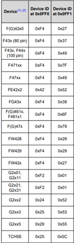
There is a table found in “MSP430 Programming with the JTAG Interface” www.ti.com/lit/pdf/slau320 [ti.com] section 2.6 “JTAG features across device families”, that lists the device ID address and value for different devices. There are a few tables in this section as for the Flash vs the FRAM families there are different locations that this is found. The JTAG tool actually reads the device ID before programming so it can use the right memory map, JTAG features, etc for that part – so usually in CCS or other program you are using with your programmer, it knows what device you have set it up to be trying to access and then it checks that when it reads this address it gets the expected value for that device ID and will throw a warning if it does not match.

 The TLV in INFO A is a bit different – on the Gxx parts that is stored in user-accessible flash and could be erased – it contains calibration info, but not the device ID because the device ID needs to be somewhere that it cannot be accidentally erased (since it is used by JTAG etc and you need to always be able to access/recover the part).

[Customer]

I finally tried the Elprotronic instruction F_Get_Device_Info() today.  Turns out it doesn’t do what I thought.  Prior to configuring the device per what we know to be the device ID, that command just produces the same garbage text no matter what MCU is attached.  Documentation says “Desired index processor should be first set in the configuration …).

 I did some playing around with MSP430G2553, and the table Katie referred to.  I must be missing something.

 According to https://www.ti.com/lit/ug/slau320aj/slau320aj.pdf [ti.com], I should be able to read two bytes at 0x0ff0 and 0x0ff1 and get the code 0x2553:

 But, according to the datasheet,

 The memory map shows that 0x0ff0 and 0x0ff1 is not addressable memory. I’ve tried to read those bytes and the Elprotronic F_Memory_Read_Data()  function returns a fail status code.

 I am guessing I might find a Device ID in the Information memory, but the datasheet doesn’t supply a map of that except for segment A.  But the apparent conflict between the two documents is puzzling.

[TI/Elprotronic]

It is possible to read any MCU location  but first it must be connected with MCU using Open Target Device funcion. If response is correct tben Read memory from specified address should reply. We can connect via M.Team in the next week and check what is done not orrrectly in your side, or email me sequence functions you are using then we can check it now.

[Customer]

I am looking for clarification on the address to read device ID and what constants to expect.  The MCU we use in all our products are MSP430G2553, MSP430G2402, MSP430G2475.  Address 0x0ff0:1 does not work.

 We wish to improve this: get the device ID correctly and reliably for both.  We have other processors to handle in the future, and data is going into a database.

COMMENTS AGAIN WELCOMED!

TY,
CY


  • Hi CY,

    Does customer check the All the ID codes in MCU: 0xFF0 & 0xFF1

    I will take a look at some MSP430 devices (I might do not have the same device customer used) and check whether the device ID is correct to the table.

    B.R.

    Sal

  • Different MSP430 family (2xx / 5xx / FRAM) have different JTAG ID. When right family (based on JTAG ID) is selected, part can be recognized by Device ID. How all this is done, can be found in open source MSP Debug stack (https://www.ti.com/tool/MSPDS), because automatic device detection / recognition is supported by TI tools (over msp430.dll). However, don't know about Elprotronic functions for this.

  • Folks - we appreciate your input as we yearn to understand this further.  The follow on question is:

    “With a G2553, when one reads address 0xff0, the read function returns an error code.  The G2553 datasheet says oxff0 is in non-addressable space.”

    Comments?

    TY,
    CY

  • I read without issue G2553 word from 0x0ff0 with another SBW master or device itself (mov.w &00FF0h, R15).

  • Hello,

    I am still very curious, to be honest. 


    • Whatever SBW “master” device being use might not throw an error like Elprotronic does, it might be giving garbage data. 
    • Assembly instruction mov can’t fail, it will happily move something to R15. 
    • It would be helpful if you could share what value you are reading in both methods and if they agree.  If 0xff or 0x00 then we may be skeptical. 
    • No one has explained away the apparent discrepancy of address 0xff0 in the two tables at the top of this E2E thread.  ?
    • Even if you are in fact reading good data from 0xff0, it may not help since the Elprotronic instruction F_Memory_Read_Data() is returning an error code


    Maybe Device ID is in the Information memory, but the datasheet doesn’t supply a map of that except for segment A.  Maybe getting that information would be helpful.  ?

     We really appreciate everyone helping on this.

    TY,
    CY

  • I made a unique simple binary MSF430G/F2xx UART hello world that display also device ID (mov.w &00FF0h, R15), and it is working for any 2xx device, for example 2553, 2955, 2272... This is related to running program on device itself, without anything connected. I didn't test it in debugging mode, but in free running it definitely move right value, not something to R15.

    If we are talking about SBW master, than any SBW MSP (LP eZ) FET will read this 0x0FF0h value, because it is used to detect device or to check if selected is the right one. It is part of (open source) MSP Debug Stack FET firmware. It also can be found in open source replicator (slau320).

    I never used Elprotronic devices, so don't now about F_Memory_Read_Data() specification, but whatever they (Elprotronic) do, for device detection (PC/GUI side) must be used the same procedure (reading 0x0ff0 from master) because there is no other way.

    In any case, device ID location on any MSP430 it's not related to info memory.

  • ZMO great work !
    From customer ----

    "

    Mystery Solved!


    Adding Gregory


    The Elprotronic User Guide, describes the function I’ve been using F_Memory_Read_Data() as “Read data block from Flash Memory only.”


    Elprotronic supports alternate functions:

    • F_Read_Word() described as “Read one word ( two bytes) from RAM, registers, IO, Flash etc.”
    • F_Read_Byte() described as “Read one byte from RAM, registers, IO, Flash etc.”


    So I tried the alternates, and they work.  Experiments in the lab showed:


    // For G2553, device ID (two bytes)

    ReadBytesStatus = MSP430FPA.F_Memory_Read_Data(0x0ff0, 2, out deviceID); // after this instruction, deviceID = 0x0000, ReadBytesStatus = 0

    ReadByte = MSP430FPA.F_Read_Byte(0x0ff0); // after this instruction, ReadByte = 0x25

    ReadByte = MSP430FPA.F_Read_Byte(0x0ff1); // after this instruction, ReadByte = 0x53

    ReadWord = MSP430FPA.F_Read_Word(0x0ff0); // after this instruction, ReadWord = 0x5325


    So I think the lesson here is the address 0x0ff0 is not flash.  It is something else, or at least the Elprotronic thinks so.  I tried F_Memory_Read_Data() on a RAM address and got the same failure code.  So I figure F_Memory_Read_Data() is optimized for flash and that’s why they offer it, maybe it’s faster or something. 


    Of course the Endian thing is flipped from the TI definition, I can live with that Wink


    Thanks again to all who helped! Especially zrno soli on the forum.

    "

    TY,
    Chris

**Attention** This is a public forum