This thread has been locked.

If you have a related question, please click the "Ask a related question" button in the top right corner. The newly created question will be automatically linked to this question.

MSP430FR6047: Measurement problems of liquid flow in pipelines of different materials

Part Number: MSP430FR6047

Hi Team,

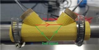
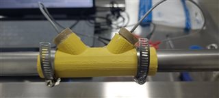
Currently, the customer is testing the adaptability of the flow meter to pipes made of different materials. The transducer installation method used is a "V" type installation, as shown in the figure below:

When the device is installed on a PVC pipe, it seems that two distinctive lobes can be seen on USS GUI. When the Gap between pulse start and ADC capture parameter is 40, the waveform is as follows:

When the Gap between pulse start and ADC capture parameter is 80, the waveform is as follows:

When the Gap between pulse start and ADC capture parameter is 60, we can clearly see the boundary between the two lobes:

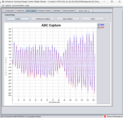
However, only when the Gap between pulse start and ADC capture parameter is 80, the displayed lobe can be used for flow calculation correctly, that is, the second lobe can be used for flow calculation. The signal strength of the first lobe seems to be low, and GUI will report an error and cannot perform calculations.

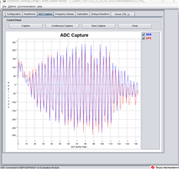
The customer's current problem is that when they put the measuring device on the stainless steel pipe, there is only one wave lobe seen by GUI. When the Gap between pulse start and ADC capture parameter is 40, the waveform is:

This waveform cannot be used for flow calculation and errors will be reported frequently.
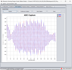
But when the Gap between pulse start and ADC capture parameter is 80, there is no second lobe like the PVC pipe, but a bunch of messy signals, as shown in the figure below:

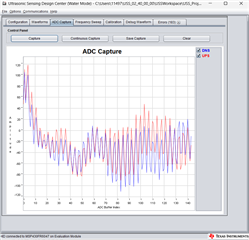
Therefore, the device cannot perform flow measurement on stainless steel pipe. What may be the cause of this problem and what are the solutions?
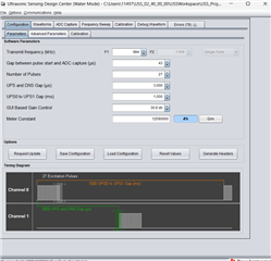
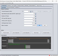
GUI configurations:

--

Thanks & Regards

  • Hi Yale,

    It seems that the 1st signal is passing through the pipe surface. The distance is short and speed is fast. It seems to be the ringing of the excitation signal. 

    The 2nd signal should be correct receive signal which pass through the pipe and reflected back to the transducer. For the steel pipe, it will significantly reduces signal energy when passing through it. So, it make sense that the 2nd signal is hardly to receive on steel pipe. 


    And could you check if the customer is using ultrasonic gel between the transducer and pipe. It could help on receiving a good signal.

    Best regards,

    Cash Hao

  • Hi Cash,

    Thank you for your reply regarding the signal issue, it has been very inspiring to me。

    Regarding the issue of ultrasonic coupling agents, I am using industrial lubricating grease as the ultrasonic coupling agent. I am not sure if this issue is caused by industrial lubricating grease.
    Do you have any suggested solutions to the current problem? For example, replacing a stronger ultrasonic transducer or choosing a better coupling agent?Or switch to the installation method of a transducer?

    Best regards,

    wang

  • Hi Wang,

    From my side, the biggest issue is the pipe material. With steel pipe, it is hardly to receive a decent signal no matter what transducer and coupling agent you are using. 

    We have some experience on PVC pipe for this kind of clamp on meter. And we have tried on steel/copper pipe before, but we failed to find a workable solution for this kind of pipe. 

    https://www.ti.com/lit/an/slaa949/slaa949.pdf

    Best regards,

    Cash Hao

  • Hi,Cash

    thank you for your answer, but I have to apply it to metal pipes. It seems that I need to find other solutions. Thank you again.

    Have a good day

    Wang

  • Get it. I will close this thread now. 

**Attention** This is a public forum