This thread has been locked.

If you have a related question, please click the "Ask a related question" button in the top right corner. The newly created question will be automatically linked to this question.

MSP430F6736A: ADC not work after reset the watchdog reset

Part Number: MSP430F6736A

When the ADC was interrupted and did not work properly, I tried to reset the watchdog, but the ADC still did not work after reset

  • Are you asking about the SD24 or the ADC10? The ADC10 is not reset by a PUC (including Watchdog), so it continues to do what it was doing [Ref (e.g.) User Guide (SLAU208Q) Table 27-3; note all the "-(0)" notations, which means "reset on POR, not PUC"]. It appears the SD24, by contrast, is reset by a PUC.

    If ADC10ENC is still set, there are a number of bits you won't be able to change. Probably the best strategy is to do a reset sequence -- stop then start -- in your ADC initialization function.

  • thanks Bruce!I have a problem now:my issue is about ADC10,The features I'm using now include:ADC24,ADC10,eUSCI,Timer_A and spi;My controller seems to be having problems twice a month,about ADC10 not running only.When I pass the command trigger watchdog,it's not work(now i know "The ADC10 is not reset by a PUC (including Watchdog)").so i want konw What might be the cause of this problem and you said "Probably the best strategy is to do a reset sequence -- stop then start -- in your ADC initialization function" How does it work,can you give me  more detailed approach?;thank you!

  • When I encountered this (on the F2 series) many years ago, as I recall I used a fairly blunt reset sequence resembling "ADC10CTL0=0; ADC10CTL1=0; ADC10CTL0=0;". The goal is to clear (at least) ADC10ENC, ADC10CONSEQ, ADC10MSC, and ADC10ON. 

    More generally, I got in the habit of (generally) initializing peripheral registers to known values ("=" instead of "|=") rather than relying on the Reset values in the User Guide.

  • thanks Bruce! I can reproduce the problem in the following way:

    #pragma vector=DMA_VECTOR
    __interrupt void DMA0_ISR (void) {
      switch (__even_in_range(DMAIV,16))
      {
          case  0:
            break; //No interrupt
          case  2: //DMA0IFG
          {
            //128 conversions complete
            //Disable Conversions without pre-empting any conversions taking place.
            ADC10_A_disableConversions(ADC10_A_BASE,ADC10_A_PREEMPTCONVERSION);   //  ADC10_A_COMPLETECONVERSION
            AdConvFinshFlag = 1;
          }break;
          default: 
            break;
      }
    }

    and When I'm running the simulation,I do this by setting two breakpoints in the interrupt and Step by step run,the ADC10 issue is sure to appear;I tried to reset ADC10 using your method,It didn't work either:

    if(ADC10_A_isBusy(ADC10_A_BASE) == ADC10_A_BUSY)
          {
            ADC10_A_disable(ADC10_A_BASE);  // close adc10A
            HWREG16(ADC10_A_BASE + OFS_ADC10CTL0) &= ~(ADC10ENC);
            // Force reset ADC10 register
            HWREG16(ADC10CTL0) = 0;
            HWREG16(ADC10CTL1) = 0;
            HWREG16(ADC10CTL2) = 0;
            HWREG8(ADC10MCTL0) = 0;
            HWREG16(DMACTL0) = 0;
            HWREG16(DMA0CTL) = 0;
            
            InitAdc();
            g_AdcFinshTimeout = g_TickMS;
            PrintfLog("Adc Init",0);
          }

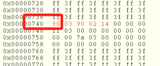
    I tried to look at the register data for ADC10,Found that the ADC10ON bit could not be reset after the reset code was executed:

    so I want to know if I'm doing the right thing, and if there's another way to force the ADC10ON bit off;thank you!

  • 1) It turns out there was one more step; the sequence was actually:

      ADC10CTL1 = 0;
      ADC10CTL0 = 0;
      ADC10CTL1 = 0;
      ADC10CTL0 = 0;

    2) The additional (initial) write to CTL1 was apparently to write CONSEQ=0. This was on an F2 device, and I just noticed that in the F5 series ADC10, CONSEQ isn't writable when ENC=1, but it is in the F2. The instructions in the F5 User Guide [(SLAU208Q) Sec 27.2.7.6, Bullet item 4] appear to be the same as in the corresponding section in the F2 Series UG [(SLAU144K) Sec 22.2.6.6], so I'm not sure what they had in mind there.

    3) I don't have one of your devices, so you might need to experiment.

    4) Unsolicited: I'm not sure you should condition this on ADC10BUSY, since the ADC might be momentarily idle (between samples), but still active. I suggest you always do the reset sequence, since it's (presumed) rare and doesn't cost that much.

  • Thank you for your patience! Bruce! i tried to handle the simulated failures the way you did,When the ADC is not working, the reset sequence also cannot be reset ADC10;Are there other ways to reset the ADC if it is not working Except for  POR or RST pull down?When I use the reset sequence, the ADC10ON bit is still on. Is that the reason why it can't be initialized again?One more question:When I use a single channel to repeat the conversion, I want to switch the channel after this conversion. Is the following operation correct:

    void SetAdChannelNo(uint8_t AdNo)
    {
      AdConvFinshFlag = 0;
      AdValueType = AdNo;
      AdCurChannel = AdNo;
          
      HWREG16(ADC10_A_BASE + OFS_ADC10CTL0) &= ~(ADC10ENC);
      
      while((HWREG16(ADC10_A_BASE + OFS_ADC10CTL1) & ADC10BUSY));
      
      ADC10_A_enable(ADC10_A_BASE);  // open adc10A
      ADC10_A_configureMemory(ADC10_A_BASE,AdCurChannel,ADC10_A_VREFPOS_AVCC,ADC10_A_VREFNEG_AVSS);
    
      ADC10_A_startConversion(ADC10_A_BASE,ADC10_A_REPEATED_SINGLECHANNEL);  
      
    }
    

    thank you!

  • 2) That sequence for switching channels looks about right based on UG Sec 27.2.7.6. But I don't have an F5/F6 device with an ADC10, so you'll have to try it and see.

    1) If ADC10ON doesn't clear, that suggests that ADC10ENC is (or at least was) still on when you tried to clear it. The UG doesn't seem to say, but it's possible ADC10ENC stays on until the ADC10 (finally) stops. Maybe you need to spin on ADC10BUSY (or maybe ADC10ENC) before setting ADC10ON=0.

    I just noticed that ADC10_A_disableConversions (with preempt==true) will set CONSEQ=0 even when (presumably) ENC=1, so maybe that restriction [UG Table 27-4] isn't real. That said, the subsequent "else if" test looks suspicious (always true?) so maybe that function works by accident.

    [Edit: What are the symptoms of "doesn't work"? I have been assuming you encountered Erratum ADC42 [Ref Errata Sheet (SLAZ646S) p 6] by setting ADC10SC (after the PUC) while the ADC was active; but maybe it's something different?]

  • thanks Bruce! I determine the BUSY state before start the next conversion;However, it still occurs that the ADC does not work(I intentionally interrupted the ADC timing when I set a breakpoint in the DMA interrupt,The purpose is to simulate the ADC failure;ADC-associated DMA interrupts cannot be triggered);When it is determined that the ADC is not working,I noticed that the BUSY state was always set;I waited for more than ten minutes and it was still set;and using the reset sequence does not reset the ADC.Now I want to know how do I reset the ADC by software when the ADC is not working?

  • I don't know any (out-of-band) mechanism for resetting the ADC10. I think the only way is to "de-initialize" it. That would mean (a) set CONSEQ=0 [maybe?] (b) set ENC=0 (c) make sure BUSY=0 (or maybe ENC=0) (d) clear all the rest of the fields.

    I'm not sure I see how breakpointing in the DMA ISR would trigger (simulate) an ADC hang. If you stop the DMA, I think the ADC will keep running (dropping the samples). That said, your memory display above seems to say you're using SSEL=MCLK, which would certainly be stopped at a breakpoint.

    Or are you observing that the hang happens after calling the switch-channel function you posted above? Originally you were talking about a Watchdog reset.

**Attention** This is a public forum