This thread has been locked.

If you have a related question, please click the "Ask a related question" button in the top right corner. The newly created question will be automatically linked to this question.

ADC sampling bit in MSP430G2553

Other Parts Discussed in Thread: MSP430FR5739, MSP430G2553

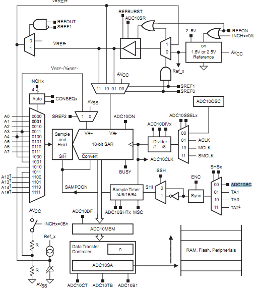
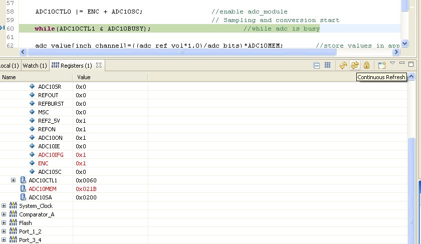
I started using ADC module of MSP430 & do its settings as recommended. But when set its ADC10SC bit in the program by  "ADC10CTL |= ENC + ADC10SC", it do not get high in register column during debugging.. But still my ADC10MEM shows right result. My question is when my sampling bit do not start, how the conversion occur.

I am new to this controller, I might be missing something. Kindly help.


Thanks & Regards

Deepak Bansal

  • Hello Deepak Bansal.

    theoretically this register can be read by the compiler registers.

    Below is the block diagram of the A / D and also leave a link to theuser's guide of the family msp430x2xx.

    I would like to know what compiler are you using our reed?


    http://www.ti.com/lit/ug/slau144h/slau144h.pdf

  • Hi Rodrigo Rodrigues Teixiera

    I am using CCSv4.


    Thanks & Regards

    Deepak Bansal

  • Come on then!


    I did a test and it worked normally MSP430FR5739 change the state of register usually

    see below.


    see you soon.

  • Hi Rodrigo, I have used MSP430G2553. You can see that after instruction "ADC10CTL |= ENC+ ADC10SC"The register values changes & ADC10Sc do not get set

    See below:

  •  hello,

               may be in ur instruction '+' sign is interpreted as binury plus so  check it. and   see that in ur registers adc10ifg is set.means interrupt is generated. so hardware may clear adc10sc bit.

  • Hi Hardik,

    As you can see in above snapshot adc10ifg bit gets set. & sign you were talking about works good in all other cases.


    Thanks & Regards

  • Deepak Bansal said:
    But when set its ADC10SC bit in the program by  "ADC10CTL |= ENC + ADC10SC", it do not get high in register column during debugging.

    Know your tools! :) In this case the (de)bugger and how it works.

    When you set ADC10SC, the ADC conversion starts. Unless you have heavily changed the ADC configuration, the ADC is running on its own oscillator, and while the debugger is busy stoping the CPU, fetchign variables etc, which is a very slow process (compared with processor operation), the conversion was already completed long before the debugger checks the register content.

    Don't forget that the ADC is a separate piece of hardware. If you need synchronisation between the ADC and teh debugger, you'll need to clock the ADC by e.g. SMCLK and tell the debugger to stop the clocks. Else the ADC will just don't care for your breakpoints and debugger activity and will be done long, long before you will be able to see anything on your PC.

    Always keep in mind that the debugger cannot freeze time, and things that are happenign in real-time will cmplete in real-time, whether you have stopped the CPU by teh debugger or not.

  • Jens- Michael Gross,

    many thanks for your reply.

    Does it means that even no of Clock cycles (Target menu -> Clock) shown by debugger is approximate. How much I can trust on it.


    Thanks & Regards

    Deepak Bansal

  • I don't know how this no of clock cycles is determined. So I cannot say how correct it is.
    The MSP giving the JTAG commands for stopping the clock etc. is worst case only as fast as the MSP it has under control. Or maybe even slower, since it is usually only a 1612 with up to 8MHz)

    I fear, this detail is an information that only one of the debugger coders can give.

    Well, if I want to know the clock cycles, I usually use an I/O line and check it with a scope. I never tortured an MSP or one of my MSP firmwares with a debugger. :)

  • HI Michael

    Thanks for your reply.


    Regards

    Deepak

**Attention** This is a public forum