MSP430FR6047: About the parameter “Gap between pulse start and ADC capture“

Part Number: MSP430FR6047
Other Parts Discussed in Thread: TIDA-01486

Tool/software:

Hi everyone, thanks a lot for all the help you guys gave me in the last thread, all in all I can now get the TIDA-01486 working well with the evm430fr6047.
I'm now working on the traffic stability issue, and I have to say that TI's traffic algorithm works very well, but I'm having some problems with the parameter “Gap between pulse start and ADC capture”.

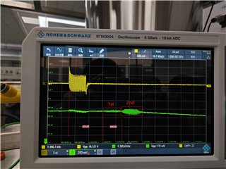
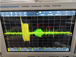
First of all to describe my measurement environment, I use a V-type external clamp mount on ppr pipes, so there will always be some signal propagating along the pipe rather than through it, like below.
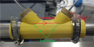
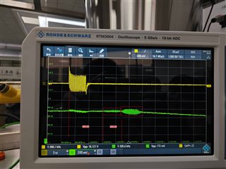
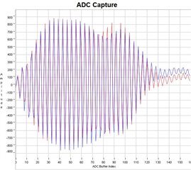
As you can see, and this is proven on the oscilloscope, it seems to me that it is only the back flap that carries the flow information.In the captured waveform of the OP, I can't guarantee that there is a 0 offset waveform in the captured waveform due to the presence of the previous waveform, which doesn't match TI's requirements, like the following.The following figures show the waveforms with “Gap between pulse start and ADC capture” set to 50us and 70us, respectively.
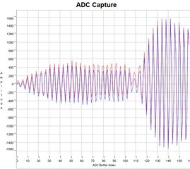
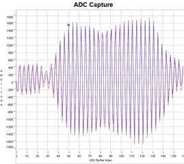
I tried hard to remove the effect of the previous waveform by changing the value of “Gap between pulse start and ADC capture”.

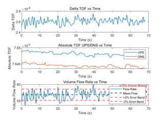
I tried to eliminate the effect of the previous waveform, by changing the value of “Gap between pulse start and ADC capture”, I found that the stability of the flux calculation is very different with only 1us difference in this parameter, for example, the following graphs are 74us and 75us for this parameter respectively. For example, the following graphs show the waveforms and the flow calculation for 74us and 75us, respectively, and you can see that there is a very big difference, which is a disaster for our design, and we can't determine a good parameter.
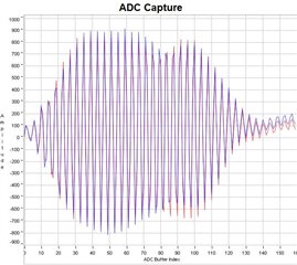
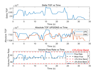
It is worth noting that they were all measured in the same measurement environment and at the same flow rate, even with no more than five minutes between the start of measurements

So here's my question.
1. what is the difference between these two waveforms from the point of view of the ti algorithm and why are they so different
2. we tried to modify the parameters in the algorithm, such as the threshold for the capture algorithm and things like that, but couldn't get anywhere, can you give some advice?
3. For a V installation, only the latter waveform is really the propagating waveform in the water flow. Am I understanding this correctly as we can barely see the rear waveform in stainless steel piping and I would like to confirm this

Any reply I will be very grateful!
Best Regards

  • Hi Scarecrow,

    1) The gap between pulse start and ADC capture just indicates the time from when the programmable pulse generator starts generating excitation pulses, and when the ADC on the other end begins to sample and capture the incoming signal. I would say that the difference in measurements from the 1us change is that the algorithm sees a slightly different proportion of the actual pulses vs the short time before the pulses arrive, changing the detection of the start of a grouping of pulses. Which configuration results in a more accurate measured VFR? It is a little hard to tell the exact ranges of +/-3% change in your images, and I am unsure what your actual flow rate is.

    2) I would recommend fine tuning the gap between pulse start and ADC capture, and try changing the envelope crossing threshold to account for the interference of the first and second signals.

    3) I am not 100% sure I understand your question so if it seems so, please elaborate. But to answer - The 2nd signal as labeled in your image is the one that we would like to measure to find the VFR. When you say the rear waveform, you mean the 2nd signal / the reflected one? I am surprised to hear that stainless steel does not reflect the signal well, assuming I am understanding your question correctly.

  • Hi Dylan,

    Thanks for getting back to me.

    1. For the first question, we did some processing on the images here, so please ignore the 3% error band here. I will try to explain to you as much as I can about the problem I am having.


    First of all, for a 75us interval, we can see a significant difference in the time of flight between the UPS and DNS, and this difference represents the flow rate in the pipe. At the same time, we have analyzed the data Dtof values that also fluctuate pretty much above and below this difference, which is something we can pick up.


    However, for a time interval of 74us, the situation changes and you can see that even at the same flow rate, the flight times of UPS and DNS do not have a significant difference and almost overlap. And, he can't correspond to the value of Dtof, which causes problems for our next processing.

    In fact, when the “Gap between pulse start and ADC capture” is 75us, it clearly produces a more accurate measurement of the VFR.

    2. By threshold do you mean the algorithmic threshold that is adjusted in USS_userConfig.h using #define USS_ALG_RATIO_OF_TRACK_LOBE, we tried to adjust the value from 0.1 to 0.2, but couldn't get anywhere.
    The problem at the moment is that I don't quite understand what's happening, what causes a 1us time interval to make the calculated data so different between the two times.

    3.I'm sure you understand correctly that the waveform behind what I'm talking about is the 2nd signal/reflected signal.

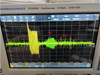
    You can see such a big difference between ppr pipes and stainless steel pipes in the picture.

    The left picture is ppr pipe signal, the right picture is stainless steel pipe signal

  • Looks like I accidentally uploaded two pictures of the signal in the stainless steel piping, sorry about that.

  • Thanks for elaborating on these points. 

    1) I see, so the 75us produces a better VFR. I see there is a nonzero VFR so this does look like it is working better.

    2) By envelope crossing threshold I was referring to the nonemclature used in the USS GUI. In the source code we use the defines - USS_ALG_ABS_TOF_HILB_CROSS_THRESHOLD and USS_ALG_RATIO_OF_TRACK_LOBE. Looking at the USS design guide, it appears that changing the envelope crossing threshold should only affect the hilbert and hilbert wide algorithm options. Which algorithm have you chosen to use? I also do not mean that increasing the envelope crossing threshold will definitely make the 74us vs 75us results the same. My point was just that this would affect the detection of the start of the pulses and therefor affect the calculated times of flight. 

    3) Yes thanks for the images to clarify, I understand. Have you tried this with other sizes of stainless steel pipes? I wouldn't expect such a poor reflected signal.

    The bottom line is, is it important to include a small amount of time before the pulses begin in your ADC capture to most effectively capture the envelope of the received pulses. I would recommend continuing to experiment with the gap between pulse start and ADC capture setting to see what gets you the most effective VFR calculation. Additionally, adjusting the envelope crossing threshold can allow you to ignore some of the pulses from the 1st signal to get a better reading. These measurements are highly dependent on setup and environment so oftentimes finding a configuration that suits your application needs can require quite a bit of trial and error. 

    Another recommendation that I have is to see if you have some way to mitigate the 1st signal as this seems to be disrupting what would otherwise be an effective transmission. Changing the physical layout of the transducers may help to at least have the 1st and 2nd signals arrive further apart, allowing you to measure the intended 2nd signal more easily.

  • Hi Dylan,

    Thank you for replying to me. I'm going to describe my problem further.

    1) I am using the example project of uss for ultrasonic water flow measurement, so the algorithm used should be Lobe algorithm.
    I don't see “envelope crossing threshold” used within the program, and as you say, this parameter probably only affects the Hilbert and Hilbert Wide algorithms.

    For the lobe algorithm, what parameters should I change to allow the algorithm to ignore some of the pulses in the first signal as much as possible to get a better reading?
    Also, you mentioned USS design guide, can you provide a valid link for me to view it. I am using EVM430FR6047 so I downloaded Ultrasonic Design Center from the website. https://www.ti.com.cn/cn/lit/pdf/slau720?keyMatch=USS%20design%20guide&tisearch=universal_search However, it does not provide any information on envelope crossing threshold.

    2) Regarding, the stainless steel pipe, we didn't test too many sizes, the pipe we are currently using has a diameter of 25mm and a thickness of 1.5mm. i think that this is enough to calculate the flow rate, but this is not the case.
    I am working on some information to adjust the physical layout of the sensor and the structure of the test fixture to minimize the first signal. But at the same time, we would like to be able to eliminate the effect of the first signal in software, so I need to ask you for help with any software configurations that can eliminate the effect of the first signal as much as possible.

    Best Regards!

  • Hi Scarecrow,

    Sorry I thought I had inserted a link to the design guide, USS Design Center User's Guide. This guide has a lot of helpful information. Additionally, the USS Software user's guide will likely be helpful to you.

    To ignore some of the pulses in the first signal, the envelope crossing threshold was my primary idea. Have you tried reducing the number of pulses a bit so the pulse-train has a shorter duration, and hopefully interferes less with the 2nd signal? This would be worth experimenting with. In the past I have seen some users add a resistor between the USS channel terminals to reduce the ring-down time as well, which may help to attenuate the tail end of that signal and help to improve your measurement. Of course this would also attenuate your 2nd signal, so may be detrimental.

    Thanks for the information on the hardware set up. Would you mind informing me what your targeted error % threshold is for VFR?

  • Hi Dylan,

    Thank you for your reply!
    I read within the design guide about envelope crossing threshold. If I understand correctly, I'm now using the LOBE algorithm, so I should modify USS_ALG_RATIO_OF_TRACK_LOBE.


    As far as reducing the number of pulses, I am now at 25, I will try to reduce this value and share the experimental results with you next time.

    For us, the target error percentage threshold for the VFR is now 3%, of course, we definitely want to be able to be more precise, but for now, we set it at 3%. What worries me more is the repeatability error, he can be calculated by the following formula, under the current test conditions, this value is more than 10%, however, our target is 1%, and the current value is far beyond our target! I guess this is due to the instability of the signal and I'm trying to fix this.

    Thanks so much for your response!Merry Christmas in advance!

    Best Regards!

  • Correct on your first note.

    Also, thanks for explaining your accuracy needs. I think that if we are able to address this issue with the first signal interfering with the second we should be able to improve your accuracy AND repeatability measurements. Also, I am curious how many samples you use when you get a repeatability error of 10%?

    Lets see if we can address the root cause then we will see how much we can improve the accuracy and repeatability.

    Please update the thread once you've been able to experiment a bit with the changes.

    Merry Christmas!

  • Hi Dylan,

    I did some testing during this time.

    To answer your first question, these statistics were obtained from 2000 collection samples, and since the EVM fires in 500ms, the total statistical time was about 16.5 minutes.

    Based on this period of testing, raising the threshold and reducing the number of pulses does improve the repeatability error's. I use 15 number of pulses with the threshold set to 25 and the repeatability error is around 7%.

    But I think the biggest problem is the stability of Dtof. To represent the stability of UPS, DNS, and Dtof, we use a metric called the coefficient of variation, which can be calculated by dividing the standard deviation by the mean to eliminate data discrepancies of different orders of magnitude. the coefficient of variation for UPS and DNS is around 0.004, but the coefficient of variation for Dtof is around 2. This means that the data for dtof is quite discrete, which I think is the main reason for the high repeatability errors in traffic.
    What is your assessment of the root cause of this issue? Should I consider modifying my hardware? Is the noise affecting the integrity of the algorithm calculations?

    The other main issue is the 0 flow error, in the current measurement environment the dtof at 0 flow is about 5000pf which is not normal, I am still checking for information on how to solve this problem, is it entirely due to a path mismatch in the hardware? Is there a way to improve the problem in software? Also, I have observed a strange phenomenon that the number of pulses affects the dtof value at 0 flow, for example:
    10 pulses ----->dtof 6500 ps
    20 pulses ----->dtof 5500 ps
    25 pulses ----->dtof 4700 ps

    Do you have any insight on this matter? I would appreciate any insights you might have.

    Best regards.

  • Thanks for the information.

    My suspicion is that start of the 1st signal is being used as the start of the overall waveform, and the end of the 2nd signal is being used as the end of the overall waveform, at least for one of either the upstream or downstream signals. It is possible that the zero flow error youre describing is caused by a path / impedance mismatch, but the large coefficient of variation seems like the issue is more than an impedance mismatch. Of course I have not seen your PCB or full hardware setup but I think it would be easy to tell if the paths are very different.

    My perspective is that the interference of the 1st signal with the second is causing a lot of issues, so some hardware adjustment to avoid that would be best. Earlier you pointed out that the PPR pipe did not have the same problem, is it possible to continue using PPR? Did you have other issues using this material?

    The other thing you might want to experiment with is a transaxial transducer setup, so there is no 1st vs 2nd signal to worry about. Plus then you typically get a better signal strength. 

    I am sure there are other hardware adjustments you can make to mitigate the issue, like the ones I mentioned earlier in the thread. Let me know if there is some issue with making the adjustments I mention. I think that you already have most of the software pieces above that you can use to try to ignore the 1st signal, and I see you've been experimenting with them above.

    Perhaps you could try using the 1st signal to measure the time of flight / flow - you could shorten the ADC capture window and set it to end before the 2nd signal arrives and see what kind of results you get with this configuration. If you aren't open to the adjustments above you could try it.

  • Hi Dylan,

    We evaluated our PCB and the two paths are really quite different now. In TIDA-01486, chx goes through two different drive and receive paths.  Our design follows this, which means that the two paths of ch0 and ch1 must match exactly, but as you know, matching exactly is difficult, so I'm trying to use a multiplexer to make ch0 and ch1 share the same receive and transmit paths.This might have some effect.

    My suspicion is that start of the 1st signal is being used as the start of the overall waveform, and the end of the 2nd signal is being used as the end of the overall waveform, at least for one of either the upstream or downstream signals.

    That's the point you're making, that's really a whole new angle, we hadn't considered that. Is there any way to verify this, you know the algorithm is a black box for us, is there any interface to see the process parameters used in the algorithm, such as where the algorithm locks the flaps and so on. We have adjusted the time window of the adc samples to show only the second signal and the issue still exists.

    The sad news is that we are having the same problem with ppr pipes. And we can't use the transaxial transducer setup, we have to go with the V mounting path.

    Either way, I'll try to modify my hardware and find a way to fix the problem. Thank you very much for your advice and I'll share it with you once I've made progress.

    Best regards.

  • Understood.

    Since we are already having trouble with the TOF calculation this might not help, but you could use the absolute times of flight and compare to the oscilloscope capture to see if the reported absolute times are corresponding to the start of signal 1 or 2, which would help shed some light on which signal is actually being used. 

    Noted about needing to continue using the V setup. If your continued testing reaffirms that the signal 1 and 2 are interfering and "confusing" the algorithm, maybe another hardware change that could help is adjusting the angle of the V so that the gap between the 1st signal ending and the 2nd signal arriving is greater? Then you could adjust the ADC capture window to only collect one of the signals.

  • Great advice and that's exactly what we should do next.

    I have a basic idea of what approach I should take to solve my problem, and over the next little while, we will be upgrading our setup, including improving the hardware and the angle and mounting structure of the transducer.Our colleague in charge of the software is working hard to try to eliminate the interference between the two signals.

    Thank you so much for taking the time to answer my questions. I really appreciate it!
    Wishing you all the best!

**Attention** This is a public forum