Part Number: MSP430F6776A
Tool/software:
Hello,
I'm new with embedded systems and am trying to get a LCD board lit up with an MSP chip as master and LCD as a slave.
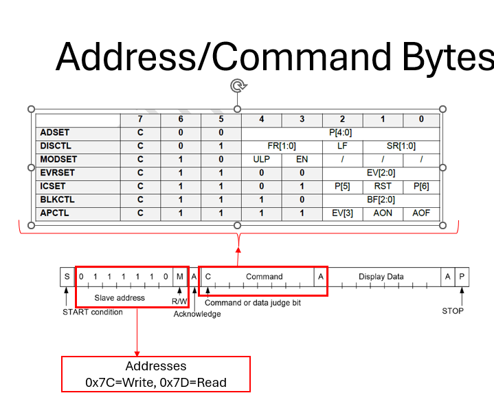
I've used the Command register (on page 6 in the doc) to turn on and off all LCD segments but cannot light up specific ones.
Page 9 of the doc shows an example of setting this up and I have data on my protocol analyzer with the transaction going through.
My transaction data is ICSET -> ADSET -> what bits in the first 2 segments I want to display. Which matches the example, but doesn't work.
What am I missing?
Thanks.
LCD board documentation
Code#include <msp430.h>
#include <stdio.h>
unsigned char TXData;
unsigned char TXByteCtr;
unsigned long TXDataBuffer[]={0x58,0x00,0xE8}; //These are sent in reverse order
//0x58,0x00,0xC8,0xE8
int bulkTX = 0;
unsigned long TXDataBufferSingle;
void main(void)
{
WDTCTL = WDTPW | WDTHOLD; // Stop WDT
// Setup P2.5 UCB0SCL, P2.6 UCB0SDA
P4SEL0 |= BIT4 | BIT5; // Set P4.4,P4.5 to UCB1SCL, UCB1SDA
//Setup LCD_PWR_EN
P5DIR |= BIT0;
P5OUT |= BIT0; //Turn on LCD power
__delay_cycles(6000); //Delay for LCD power to startup, review timing
// Setup eUSCI_B0
UCB1CTLW0 |= UCSWRST; // Enable SW reset
UCB1CTLW0 |= UCMST | UCMODE_3 | UCSSEL_2; // I2C Master, use SMCLK
UCB1BRW_L = 12; // fSCL = SMCLK/10 = ~95104.5kHz, /11 = 95kHz, /12= 87kHz
UCB1BRW_H = 0;
UCB1I2CSA = 0x3E; // Slave Address is 03Eh
UCB1CTLW0 &= ~UCSWRST; // Clear SW reset, resume operation
UCB1IE |= (UCTXIE0 | UCNACKIE); // Enable TX interrupt and NACK interrupt
TXData = 0x7A; // Holds TX data, sending 0x7A for all pixels ON command to LCD
bulkTX = 0;
TXByteCtr = 1;
TXDataBufferSingle = 0x79;
while (UCB1CTLW0 & UCTXSTP) ; // Ensure stop condition got sent
UCB1CTLW0 |= UCTR | UCTXSTT; // I2C TX, start condition
__bis_SR_register(LPM0_bits | GIE); // Enter LPM0 w/ interrupts
__no_operation(); // Remain in LPM0 until all data
while (1)
{
bulkTX = 1;
TXByteCtr = 3; // Load TX byte counter
while (UCB1CTLW0 & UCTXSTP) ; // Ensure stop condition got sent
UCB1CTLW0 |= UCTR | UCTXSTT; // I2C TX, start condition
UCB1TXBUF = TXDataBuffer[2]; // first byte (0xE8)
__bis_SR_register(LPM0_bits | GIE); // Enter LPM0 w/ interrupts
__no_operation(); // Remain in LPM0 until all data
// is TX'd
//TXData++; // Increment data byte
}
}
//------------------------------------------------------------------------------
// The USCIAB0_ISR is structured such that it can be used to transmit any
// number of bytes by pre-loading TXByteCtr with the byte count.
//------------------------------------------------------------------------------
// USCI_B0 interrupt service routine
#if defined(__TI_COMPILER_VERSION__) || defined(__IAR_SYSTEMS_ICC__)
#pragma vector = USCI_B1_VECTOR
__interrupt void USCI_B1_ISR(void)
#elif defined(__GNUC__)
void __attribute__ ((interrupt(USCI_B1_VECTOR))) USCI_B1_ISR (void)
#else
#error Compiler not supported!
#endif
{
switch (__even_in_range(UCB1IV, 30))
{
case USCI_NONE: break; // No interrupts
case USCI_I2C_UCALIFG: break; // ALIFG
case USCI_I2C_UCNACKIFG:
UCB1CTL1 |= UCTXSTP; // Generate I2C stop condition because communication failed
break; // NACKIFG
case USCI_I2C_UCSTTIFG: break; // STTIFG
case USCI_I2C_UCSTPIFG: break; // STPIFG
case USCI_I2C_UCRXIFG3: break; // RXIFG3
case USCI_I2C_UCTXIFG3: break; // TXIFG3
case USCI_I2C_UCRXIFG2: break; // RXIFG2
case USCI_I2C_UCTXIFG2: break; // TXIFG2
case USCI_I2C_UCRXIFG1: break; // RXIFG1
case USCI_I2C_UCTXIFG1: break; // TXIFG1
case USCI_I2C_UCRXIFG0: break; // RXIFG0
case USCI_I2C_UCTXIFG0: // TXIFG0
if(TXByteCtr && bulkTX == 1){
UCB1TXBUF = TXDataBuffer[(TXByteCtr-1)];
TXByteCtr--;
}
else if(TXByteCtr && bulkTX == 0){
UCB1TXBUF = TXDataBufferSingle;
TXByteCtr--;
}
else{
UCB1IFG &= ~UCTXIFG; // Clear USCI_B0 TX int flag UCB1CTL1 |= UCTXSTP; // I2C stop condition
UCB1CTL1 |= UCTXSTP; // Generate I2C stop condition because communication failed
__delay_cycles(600000); //Delay between sending I2C messages
__bic_SR_register_on_exit(LPM0_bits); // Exit LPM0
}
/*
//Code below worked well, added above to send multiple bytes
if (TXByteCtr) // Check TX byte counter
{
UCB1TXBUF = TXData; // Load TX buffer
TXByteCtr--; // Decrement TX byte counter
}
else
{
UCB1IFG &= ~UCTXIFG; // Clear USCI_B0 TX int flag UCB1CTL1 |= UCTXSTP; // I2C stop condition
UCB1CTL1 |= UCTXSTP; // Generate I2C stop condition because communication failed
__delay_cycles(600000); //Delay between sending I2C messages
__bic_SR_register_on_exit(LPM0_bits); // Exit LPM0
}
*/
break;
case USCI_I2C_UCBCNTIFG: break; // CNTIFG
case USCI_I2C_UCCLTOIFG: break; // LTOIFG
case USCI_I2C_UCBIT9IFG: break; // BIT9IFG
default: break;
}
}