MSP430FR2433: Unable to Receive BSL ACK Using UART – TEST/RST Sequence

Part Number: MSP430FR2433
Other Parts Discussed in Thread: UNIFLASH

Tool / Software: CCS
Category: MCU 
Subcategory: UART BSL Entry Issue

Description:

When attempting to invoke the BSL via the standard TEST/RST sequence, the MSP430FR2433 does not respond with the expected 0x90 ACK byte after sending the UART synchronization byte (0x80).

  • Either no response is received, or the UART shows garbage data.

  • Tested with multiple USB-UART adapters and COM ports.

Steps to Reproduce:

  1. Initialize host MCU UART at 9600 bps, 8N1&8E1.

  2. Set RST low. Apply TEST high → low → high (two rising edges required).

  3. Release RST while TEST is high.
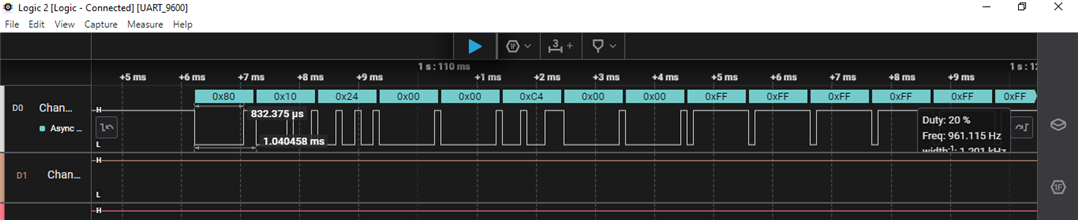
  4. Send sync byte 0x80 over UART.

  5. Observe expected ACK 0x90 from target.

Observed Behavior:

  • Sync byte is transmitted successfully.

  • Target does not send ACK (0x90).

  • Logic analyzer shows correct TEST/RST waveform.

  • UART RX from target remains idle or produces invalid data.

Expected Behavior:

  • Target BSL should acknowledge the sync byte with 0x90.

  • UART-based programming should be possible.

Methods Tried:

  1. BSL Entry via Hardware

    • TEST pin toggled twice while RST held low, TEST kept high, RST released.

    • Verified timing with logic analyzer.

  2. BSL Entry via Software
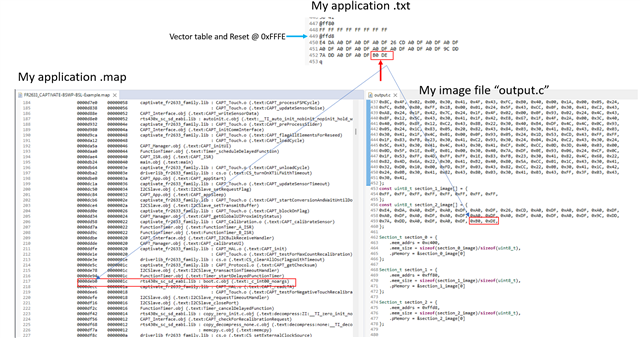
    • Jump to ROM BSL at 0x1000 from running firmware.

  3. BSL-Scripter Attempts
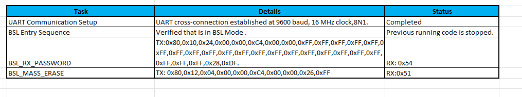
    • Script example:

  • Observed issues:

    • [ACK_ERROR_MESSAGE] Unknown ACK value after providing wrong password.

Request:

  • Guidance on why UART BSL is not responding for MSP430FR2433.

  • Confirmation on proper hardware wiring and TEST/RST timing.

  • Recommended script commands for mass erase, password handling, and firmware programming.

  • Any workarounds or updated tools to make UART BSL functional.

  • Hi Keshavamurthy,

    I'm so sorry that nobody has reached out to you with your issue.  Do you still need help with the BSL?

  • Hi Dennis,


    Yes, I still need help with the BSL.

    I am working with MSP430FR2433 UART BSL using my own driverlib-based master implementation.
    UART is configured at 9600 baud, 16 MHz SMCLK, 8N1 with proper cross-connection between host and MSP430.

    Observed Behavior

    • Subsequent commands often return error codes (0x54 header incorrect or 0x51 length incorrect).

    • Logging confirms the host is transmitting 0x80 as the first byte, but the MSP430 sometimes misinterprets it.

    • There may be an issue with packet length or checksum calculation.

    Request

    1. For FR2xx UART BSL, what is the exact definition of the Length field — does it include address + data only, or also checksum?

    2. Is my RX_PASSWORD and MASS_ERASE packet formatting correct for MSP430FR2433?

    3. Are there any known issues when running UART BSL at 16 MHz / 9600 baud?

    Any guidance or working example packet format for FR2433 UART BSL would be greatly appreciated.

    Thanks,
    Keshavamurthy

  • Hi Keshavamurthy,

    I'm setting this up on my end to reproduce the issue, but first, is there a chance your "host" is not generating the correct bit clock for 9600 baud?  Can you measure and confirm 9600 buad (104 usec per bit width)?

  • Hi Dennis,

    Thanks for the suggestion. I rechecked my UART configuration. The host side UART on the MSP430FR2433 is initialized as follows:

    static void clock_init_16MHz(void)
    {
        FRCTL0 = FRCTLPW | NWAITS_1;
        CS_initClockSignal(CS_FLLREF, CS_REFOCLK_SELECT, CS_CLOCK_DIVIDER_1);
        CS_initClockSignal(CS_ACLK,   CS_REFOCLK_SELECT, CS_CLOCK_DIVIDER_1);
        CS_initFLLParam trim = {0};
        CS_initFLLCalculateTrim(16000, 488, &trim);
        CS_clearAllOscFlagsWithTimeout(1000);
        CS_initFLLSettle(16000, 488);
        CS_initClockSignal(CS_MCLK,  CS_DCOCLKDIV_SELECT, CS_CLOCK_DIVIDER_1);
        CS_initClockSignal(CS_SMCLK, CS_DCOCLKDIV_SELECT, CS_CLOCK_DIVIDER_1);
    }
    
    static void uart_init_9600(void)
    {
        EUSCI_A_UART_initParam param = {0};
        param.selectClockSource = EUSCI_A_UART_CLOCKSOURCE_SMCLK;
        param.clockPrescalar    = 104;
        param.firstModReg       = 3;
        param.secondModReg      = 0;
        param.parity            = EUSCI_A_UART_NO_PARITY;
        param.msborLsbFirst     = EUSCI_A_UART_LSB_FIRST;
        param.numberofStopBits  = EUSCI_A_UART_ONE_STOP_BIT;
        param.uartMode          = EUSCI_A_UART_MODE;
        param.overSampling      = 1;
    
        if (!EUSCI_A_UART_init(EUSCI_A0_BASE, &param)) while (1);
        EUSCI_A_UART_enable(EUSCI_A0_BASE);
    
        EUSCI_A_UART_clearInterrupt(EUSCI_A0_BASE, EUSCI_A_UART_RECEIVE_INTERRUPT);
        EUSCI_A_UART_enableInterrupt(EUSCI_A0_BASE, EUSCI_A_UART_RECEIVE_INTERRUPT);
    }

    This gives me 104.17 µs per bit (≈ 9600 baud) with SMCLK = 16 MHz.
    As you suggested, I also measured the UART output on a logic analyzer to confirm.

  • When attempting to invoke the BSL via the standard TEST/RST sequence, the MSP430FR2433 does not respond with the expected 0x90 ACK byte after sending the UART synchronization byte (0x80).

    As this is an FRAM-based device, you should check out the FRAM BSL User Guide (SLAU550). I don't believe there are any synchronization bytes in that one. The BSL_RX_PASSWORD and BSL_MASS_ERASE commands that you are sending do not appear correct based on this user guide.

  • Hi Jackson,

    As per the  FRAM BSL User Guide (SLAU550) .I am transmitting the BSL Core Command but it is responding back as given below.

    BSL_CORE_Command TX: 0x80,0x3B,0x04,0x00. RX: 0x54,0x51,0x51,0x51
  • What you sent is not a valid command per the User Guide; see section 4.1.1. You must have the Header, two bytes which specify size, the actual command with associated data, then the two byte checksum.

    For example, BSL_RX_PASSWORD is sent as described in section 4.1.5.2. All BSL commands have examples such as these. Please read the user guide.

  • Thank you Seth for helping out on this posting.  Greatly appreciated Slight smile

    Hi Keshavamurthy, does this get your BSL working for you?

  • Hi Dennis, Seth,

    Thanks for your guidance — I’ve now corrected my packet format according to SLAU550.

    Current Status

    • I am receiving valid responses for all commands (RX Password, Mass Erase, RX Data Block, CRC Check, Load PC).

    • Packets are acknowledged with the expected 0x00 ACK header.

    • CRC check returns the correct checksum.

    So the UART BSL communication seems fully functional now.

    Remaining Issue

    After loading my firmware image (.txt format, starting at @C400) and issuing Load PC to 0xC400, the device does not appear to run the application.

    My Questions

    1. Firmware Format – I am using a TI-TXT image generated by CCS. Is this directly compatible with FR2433 UART BSL, or do I need to convert it into a raw binary/intel-hex format before programming?

    2. Start Address – Is 0xC400 the correct entry point (PC) for MSP430FR2433 applications built with CCS? Or should I be using a different vector (e.g., reset vector at 0xFFFE)?

    3. Load PC Command – After a successful program + CRC check, I send BSL_LOAD_PC (0x17) with 0x00 0xC4. The command is acknowledged, but no application runs. Could this mean my image is linked at the wrong base address, or the reset vector is not set?

    So at this point, the communication layer is solved, but I need guidance on verifying firmware image format and correct execution start address for FR2433 over UART BSL.

    Thanks again for the help,
    Keshavamurthy

  • Hi Keshavamurthy,

    Please share a copy of the TI-TXT output file for your application.

  • As requested, I’m sharing a content of  TI-TXT file generated from CCS and Array converted for application for UART_BSL. This includes the start address (0xC400 region).

    I would like add one more point that the I Verified the TI-TXT file generated by CCS is uploaded to the MCU using Uniflash Tool, while the result is Positive.

    Could you please confirm:

    1. Is the start address 0xC400 correct for FR2433 application code when using UART BSL?

    2. Does the TI-TXT format above look valid for BSL programming?

    3. Should I explicitly trigger a jump to the reset vector after load, or will BSL handle that?

  • Hi Keshavamurthy,

    Yes, the TI-TXT format is correct and the arrays also look fine.

    Yes, 0xC400 is the correct, and yes this is where the application image is placed in FRAM.  However, this is not typically where the actual application start (boot code portion of your application) is located. The location is stored as a vector in the RESET location 0xFFFE as shown below in my example, both in the .txt output file and my memory structures.    Check your application's .map file to see where this comes from. 

    I attached a ppt with the snippet below in case it is difficult to see.FR2633 example BSL mapping.pptx

    So for your application, use 0xC4C0 as the boot address.

  • Hi Dennis,

    I have made the modifications as per your suggestion.

    Now, the application is working fine when I power it using an external 3.3 V supply — it runs continuously without stopping.
    But when I power it through the LaunchPad / development board supply (USB or onboard regulator), the application starts but stops after a few seconds.

    Could this be related to the LaunchPad’s power supply or reset circuit? Please advise.

    Thanks,
    Keshava

  • Hi Keshava,

    Interesting...ordinarily when connecting the Launch pad's USB cable to power the board it should just power up and run continuously.

    But I suspect it has something to do with the SBWTDIO and SBWTCK connections between the MSP430 and the programmer/debugger and when power is first applied to the Launchpad, the debugger/programmer may be toggling these two signals in such a way as to put the MSP430 into BSL mode.

    Try the following:

    1) Hold the RESET button while connecting the USB cable to power, wait 1-2 seconds then release the RESET button

    2) Remove the SBWTDIO and SBWTCK jumpers, then cycle power on the Launchpad and see if the problem still  occurs

    3) Try programming the MSP430 with some simple code that only toggles the LED and see if same behavior occurs when cycling power

     Let me know what you find.

  • Hi Dennis,

    Thanks for the suggestions. I tried the steps you mentioned:

    1. Holding RESET while connecting USB – The application runs continuously after release.

    2. Removing SBWTDIO and SBWTCK jumpers – After removing, the MSP430 powers up and runs fine without getting stuck.

    3. Simple LED blink code – I programmed a basic LED toggle code, and the same behavior is observed (works only after RESET or removing jumpers).

    In the attached video, the MSP430 is loaded with UART BSL.

    • When powered from the LaunchPad’s onboard 3.3V supply, the code runs only for a few seconds.

    • When powered from an external RTC 3.3V battery source, the code runs continuously without issue.

    Also, when flashing the same code via UART BSL:

    • On the first flash, the firmware does not start running.

    • On the second flash (same image), the firmware runs correctly.

    This makes me suspect some difference in how the supply or reset conditions are handled during the first programming cycle.

    I have attached the UART BSL source code for your review.
    Could you please help verify:

    1. If the UART BSL implementation is correct (entry sequence, reset handling, vector table).

    2. Why the first application flash does not start, but the second flash works fine.

    3. Whether a reset/mass erase step is required after the first programming.

    Could this be related to residual SBWTDIO/SBWTCK influence during power-up, or perhaps memory initialization differences between first and second flash cycles?

    Thanks,
    Keshava

  • So it appears the issue is after programming the MSP will not start running.  Performing a manual reset or power cycle seems to make it work, correct?  Let me look into the debug/programming configuration settings.

  • 1. Normal Blink LED Code

    • First flash → runs fine.

    • Reconnect (via USB power cycle) → runs for a few seconds then stops.

    • If you press reset or remove SBWTDIO/SBWTCK (debugger lines) → code runs continuously.

    2. UART BSL Code

    • Flashing first time → not working.

    • Flashing second time → starts working.

    • Reconnect via USB power → runs for a few seconds then halts.

    • Reconnect via external RTC battery (clean supply, no debugger attached) → works, but only after 2 flashes.

  • Ok, this is good information.  I'll need to think about this and see if I can reproduce.

  • Hi Dennis,

    Thanks for your guidance so far. I wanted to give you an update:

    The UART BSL sequence between MSP430 host and MSP430 slave is now fully working. The host successfully sends commands, the slave responds correctly, and the entire sequence, including checksum verification and error handling, is functioning reliably.

    As the next step, I’m planning to implement MEC1521 as the host with MSP430FR2433 as the slave. I would appreciate any suggestions or best practices for handling the UART sequence, timing, and Zephyr RTOS integration on the MEC1521 side.

    Thanks again!

  • Hi Keshavamurthy,

    Congratulations on getting everything to finally work. Clap

    I don't know much about Zephyr or the MEC1521.

    For the host side implementation I'm not familiar with any specific practices, but I believe there are a few application notes.

    The best place I suggest checking is the following: MSPBSL Driver or library | TI.com

    On that page there is a list of documents that may not have all the answers in one-place, but enough for what you need.

    Best would be to check the web or other E2E postings on the topic.

**Attention** This is a public forum