This thread has been locked.

If you have a related question, please click the "Ask a related question" button in the top right corner. The newly created question will be automatically linked to this question.

Reset buttons are not working on the MSP430F5529 USB Experimenter’s Board

Other Parts Discussed in Thread: MSP430F5529, MSP430F5528

Hello Everyone,

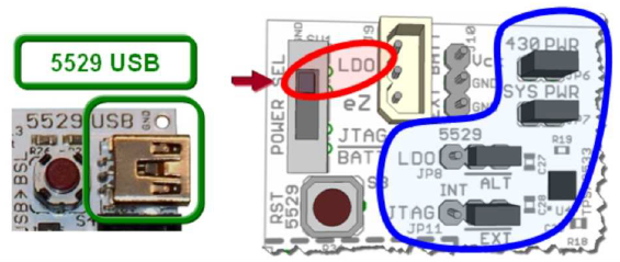
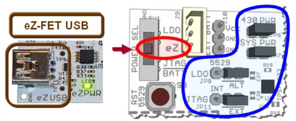
I'm testing the demo code that is pre-loaded on the MSP430F5529 USB Experimenter’s Board. When I pressed the S3 or S4 (reset) buttons, they don't seem to have any effect on the state of the processor. Do I need to change any jumpers?

Thanks

Binh


  • Binh,

    S4 is for the USB BSL (bootstrap loader).  Since the example program does not implement a USB BSL, this switch should not do anything.

    S3 should reset the device (and the LCD/backlight) if you power the board using the 5529 USB connector at the top-right of the board and the POWER SEL switch and jumpers are set as shown here:

    S3 should also reset the device (and the LCD/backlight) if you power the board using the eZUSB connector at the bottom-left of the board and the POWER SEL switch and jumpers are set as shown here:

    If you use the eZUSB configuration, you will also need to remove the TEST jumper from JP16.

    Hope this helps,

    Peggy

  • Thanks, Peggy. When I removed the Test jumper from JP16, the RST button started working. Could you please tell me more about the role of this jumper? I couldn't find much info about it in the board's user guide.

    Thanks

    Binh

  • Binh,

    According to the schematics in section 5 of the User's Guide (http://www.ti.com/lit/ug/slau330a/slau330a.pdf), the TEST jumper connects the SBWTCK signal from the eZ430 emulator to the MSP4305529 device.  This signals is one of the two signals used by the spy-by-wire communication between the emulator and the device.  When the TEST jumper is connected, the spy-by-wire communication disables the functionality of the reset button on the board.  Removing the TEST jumper disables the communication thereby enabling the functionality of the reset button on the board.  Similarly, removing the DVCC jumper disables the voltage-level translator between the emulator and the device.  This disables spy-by-wire communication and enables the functionality of the reset button.

    Hope this helps,

    Peggy

  • Thanks a lot.

    Binh

  • Hi,

    I am using the MSP430F5529 experimenters board and I see you mention in this post that the "example program does not implement a USB BSL".

    I want to try and experiment with the default USB BSL that ships with every MSP430F55xx devices (actual product would have MSP430F5528). 

    Do demo boards have BSL built in? If yes, do they have USB BSL. and if not is it possible to download the default BSL into the demo board through the FET debugger? Also, please provide links to the instructions and source code/binary of the default BSL.

    Thanks,

  • Kalyan,

    Here is more information about the MSP430 BSL (UART and USB): 

    Wiki: http://processors.wiki.ti.com/index.php/BSL_(MSP430)

    User's Guide: http://www.ti.com/lit/slau319

    Regards,

    Peggy

**Attention** This is a public forum