- Ask a related questionWhat is a related question?A related question is a question created from another question. When the related question is created, it will be automatically linked to the original question.
When configuring the ADC10 is this:
bis.w #ADC10SHT_2+ADC10ON+ADC10IE,&ADC10CTL0
bit.w #INCH_2, &ADC10CTL1
And use it to make a conversion:
bis.w #ENC+ADC10SC,&ADC10CTL0
My adc10 works as expected.
OK.
When configuring the ADC10 is this:
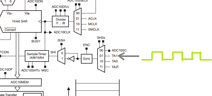
bis.w #SHS_1+ADC10SHT_2+ADC10ON+ADC10IE,&ADC10CTL0
bit.w #INCH_2, &ADC10CTL1
And the output of Timer0_A1 is this:

And use it to make a conversion:
bis.w #ENC,&ADC10CTL0
My adc10 not work. Not even enters ADC10_ISR.
........................
Am I doing something wrong?
Device: MSP430g2553
**Attention** This is a public forum