This thread has been locked.

If you have a related question, please click the "Ask a related question" button in the top right corner. The newly created question will be automatically linked to this question.

No USB FET was found when debugging MSP430F5438 Experimenter board

Other Parts Discussed in Thread: MSP430F5438, MSP430F5438A

Hi,

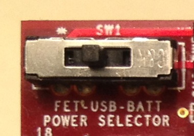
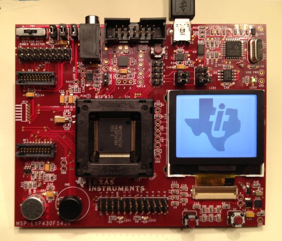
I was trying to debug MSP430F5438 Experimenter board using CCSv5, but it says No USB FET was found. I found someone said USB Interface MSP-FET430UIF is needed for debugging. I used to debug MSP430 launchpad successfully without using a debug interface, so do I need MSP-FET430UIF to debug MSP430F5438 Experimenter board? If so, why MSP430 launchpad does not require that?

Thanks!

  • Try the steps in this forum post and report your results.

    MSP 430FG439-debugging problem

    Yes, you need the MSP-FET430UIF to debug the MSP-EXP430F5438.  This is not required for the MSP-EXP430G2 since the emulatoin circuitry is provided on the LaunchPad itself.

  • Xing Dong said:
    why MSP430 launchpad does not require that?

    LaunchPad is an experimenters board, not just a processor. Many experimenter boards (not all) include a stripped-down version of the FET430UIF that provides programming and debugging capabilities for just the target processors of the board.

    The FET430UIF, however, supports all MSPs, both, 4-wire and SBW JTAG protocol, auto-adjusts to the supply voltage on self-powered targets or provides adjustable supply.itself.

  • Then what is the USB interface the board provides used for? I do not have  MSP-FET430UIF and just plugged in the USB interface but the screen of the board does not start. I found this video https://www.youtube.com/watch?v=_SwqtiAtKSM and the screen should wake up according to it. But mine is not the case.Can you help me figure this out?

    Thanks!

  • Xing Dong said:

    Then what is the USB interface the board provides used for? I do not have  MSP-FET430UIF and just plugged in the USB interface but the screen of the board does not start. I found this video https://www.youtube.com/watch?v=_SwqtiAtKSM and the screen should wake up according to it. But mine is not the case.Can you help me figure this out?

     
    In that video you can see that SW1 is all the way to the right, which means the board is battery powered.  Move it to the middle position to power it from the USB connection.  The USB interface is used to give you access to the UART on the MSP430F5438A.  You can find more details in the schematic located near the end of the user's guide.
     
  • I plugged in the USB interface and sw1 was positioned in the middle ,but the screen of my experimenter board does not wake up,it is just blinking ,why?

  • I can't tell you without knowing what code is running on the MSP-EXP430F5438.  You will need a MSP-FET430UIF to load new code to the MSP430F5438A device.

    Instead of buying the MSP-FET430UIF, consider buying the MSP-EXP430F5529.  This evaluation kit is newer and does not need the MSP-FET430UIF.

  • Hi Jason,

    I still have a few queations.

    1.The MSP-EXP430F5438 experimenter board is newly bought and I have not downloaded any code into it since I do not have  MSP-FET430UIF. But the instruction says the kit is pre-programmed, so I do not know why can't wake up the LCD screen.

    2.Also, do you mean I can debug or run MSP-EXP430F5529 simply using the board and USB interface wihout any other wires or interfaces?

    3.Do I need to buy RS232 to do serial communication if using MSP-EXP430F5529 USB experimenter's board?

    Thanks!

    ?

  • Xing Dong said:

    1.The MSP-EXP430F5438 experimenter board is newly bought and I have not downloaded any code into it since I do not have  MSP-FET430UIF. But the instruction says the kit is pre-programmed, so I do not know why can't wake up the LCD screen.

    After reviewing the schematic, did you find any other jumpers or swtiches that needed to be changed?  If it is pre-programmed, what example were you expecting to see?  This one? MSP-EXP430F5438(A) Example Software\UserExperienceDemo  It will not have the code you saw running on the YouTube video by default.  What do you observe when you power it now?

    Xing Dong said:

    2.Also, do you mean I can debug or run MSP-EXP430F5529 simply using the board and USB interface wihout any other wires or interfaces?

    This is correct.

    Xing Dong said:

    3.Do I need to buy RS232 to do serial communication if using MSP-EXP430F5529 USB experimenter's board?

    No.

  • When I power it, the LCD is blinking without any thing shown on it.

  • Are your observations the same when you power the board from batteries?  If not, explain how the results are different.

  • When I plug in the USB, the LCD is blinking dimly regardless of the way I power it. When I disconnect the USB, the LCD is off even when I use battery to power it.

  • In what position do you have the power selector switch (SW1)?


    .

    I was able to recreate the problem you decribed.  If SW1 is set to FET, and the board is powered by USB, then yes the screen will flicker.  This is an incorrect setup.  If SW1 is et to FET and the board is powered by batteries, then nothing happens.  This is an incorrect setup. 

    Any of these configurations is correct:

    SW1 set to FET, and MSP-EXP430F5438 powered from the MSP-FET430UIF.

    SW1 set to USB, and MSP-EXP430F5438 powered from the USB cable connection (best if your computer is AC powreed so it does not limit the USB current).

    SW1 set to BATT, and MSP-EXP430F5438 powered from two AA batteries (in good state of charge of course).

    I verified all of those three.  You may need to adjust the display contrast for each power source since the voltages supplied may vary slightly between them.

**Attention** This is a public forum