Hi,
Hi,
Can anyone help me in setting baud rate on BRCLK Frequency = 1,048,576 (1.05Mhz) on launchpad MSP430G2xx3 board? I modified TI example code to include changes for 1.05 Mhz clock but I don't see any change when analyzed through oscilloscope, basically signal width remains same between 1Mhz to 1.05 Mhz.. i.e., 104us.
Modified TI example code.
#include <msp430.h>
#define BAUDRATE 9600
//------------------------------------------------------------------------------
// Hardware-related definitions
//------------------------------------------------------------------------------
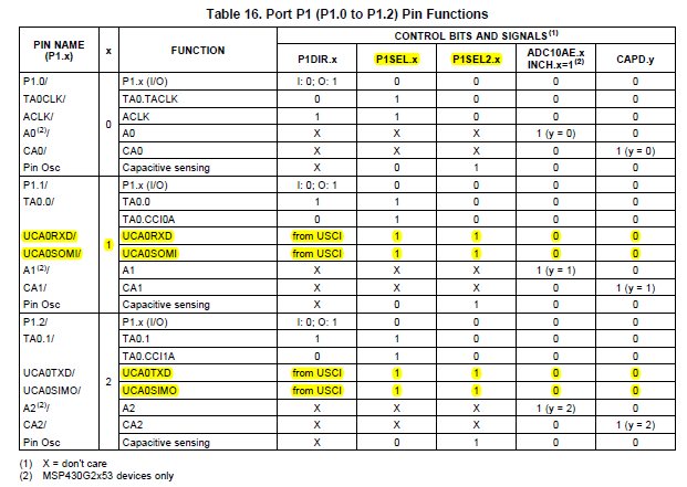
#define UART_TXD 0x02 // TXD on P1.1 (Timer0_A.OUT0)
#define UART_RXD 0x04 // RXD on P1.2 (Timer0_A.CCI1A)
//------------------------------------------------------------------------------
// Conditions for BAUDRATE Baud SW UART, SMCLK = 1MHz
//------------------------------------------------------------------------------
#define UART_TBIT_DIV_2 (1000000 / (BAUDRATE * 2))
#define UART_TBIT (1000000 / BAUDRATE)
//------------------------------------------------------------------------------
// Global variables used for full-duplex UART communication
//------------------------------------------------------------------------------
unsigned int txData; // UART internal variable for TX
unsigned char rxBuffer; // Received UART character
//------------------------------------------------------------------------------
// Function prototypes
//------------------------------------------------------------------------------
void TimerA_UART_init(void);
void TimerA_UART_tx(unsigned char byte);
void TimerA_UART_print(char *string);
int k = 0;
//------------------------------------------------------------------------------
// main()
//------------------------------------------------------------------------------
int main(void)
{
WDTCTL = WDTPW + WDTHOLD; // Stop watchdog timer
if (CALBC1_1MHZ==0xFF) // If calibration constant erased
{
while(1); // do not load, trap CPU!!
}
DCOCTL = 0; // Select lowest DCOx and MODx settings
BCSCTL1 = CALBC1_1MHZ; // Set DCOCLK to 1MHz
DCOCTL = CALDCO_1MHZ;
UCA0CTL1 |= UCSSEL_2; // SMCLK
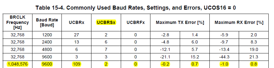
UCA0BR0 = 109; // 1.05MHz 9600
UCA0BR1 = 0; // 1.05MHz 9600
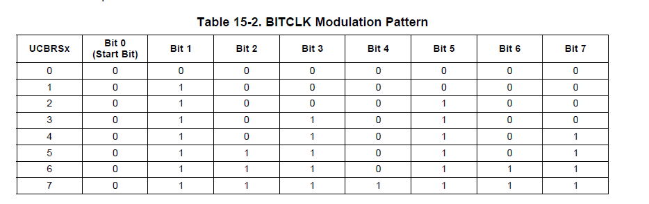
UCA0MCTL = UCBRS0; // Modulation UCBRSx = 1
UCA0CTL1 &= ~UCSWRST; // **Initialize USCI state machine**
P1OUT = 0x00; // Initialize all GPIO
P1SEL = UART_TXD + UART_RXD; // Timer function for TXD/RXD pins
P1DIR = 0xFF & ~UART_RXD; // Set all pins but RXD to output
P2OUT = 0x00;
P2SEL = 0x00;
P2DIR = 0xFF;
__enable_interrupt();
TimerA_UART_init(); // Start Timer_A UART
// TimerA_UART_print("Hello Krishna\r\n");
// TimerA_UART_print("How are you ?.\r\n");
for (;;)
{
// Wait for incoming character
// __bis_SR_register(LPM0_bits);
// Echo received character
TimerA_UART_tx('U');
for(k = 0; k<100; k++);
}
// TimerA_UART_tx(0x0f);
}
//------------------------------------------------------------------------------
// Function configures Timer_A for full-duplex UART operation
//------------------------------------------------------------------------------
void TimerA_UART_init(void)
{
TACCTL0 = OUT; // Set TXD Idle as Mark = '1'
TACCTL1 = SCS + CM1 + CAP + CCIE; // Sync, Neg Edge, Capture, Int
TACTL = TASSEL_2 + MC_2; // SMCLK, start in continuous mode
}
//------------------------------------------------------------------------------
// Outputs one byte using the Timer_A UART
//------------------------------------------------------------------------------
void TimerA_UART_tx(unsigned char byte)
{
while (TACCTL0 & CCIE); // Ensure last char got TX'd
TACCR0 = TAR; // Current state of TA counter
TACCR0 += UART_TBIT; // One bit time till first bit
TACCTL0 = OUTMOD0 + CCIE; // Set TXD on EQU0, Int
txData = byte; // Load global variable
txData |= 0x100; // Add mark stop bit to TXData
txData <<= 1; // Add space start bit
}
//------------------------------------------------------------------------------
// Prints a string over using the Timer_A UART
//------------------------------------------------------------------------------
void TimerA_UART_print(char *string)
{
while (*string) {
TimerA_UART_tx(*string++);
}
}
//------------------------------------------------------------------------------
// Timer_A UART - Transmit Interrupt Handler
//------------------------------------------------------------------------------
#pragma vector = TIMER0_A0_VECTOR
__interrupt void Timer_A0_ISR(void)
{
static unsigned char txBitCnt = 10;
TACCR0 += UART_TBIT; // Add Offset to CCRx
if (txBitCnt == 0) { // All bits TXed?
TACCTL0 &= ~CCIE; // All bits TXed, disable interrupt
txBitCnt = 10; // Re-load bit counter
}
else {
if (txData & 0x01) {
TACCTL0 &= ~OUTMOD2; // TX Mark '1'
}
else {
TACCTL0 |= OUTMOD2; // TX Space '0'
}
txData >>= 1;
txBitCnt--;
}
}
//------------------------------------------------------------------------------
// Timer_A UART - Receive Interrupt Handler
//------------------------------------------------------------------------------
#pragma vector = TIMER0_A1_VECTOR
__interrupt void Timer_A1_ISR(void)
{
static unsigned char rxBitCnt = 8;
static unsigned char rxData = 0;
switch (__even_in_range(TA0IV, TA0IV_TAIFG)) { // Use calculated branching
case TA0IV_TACCR1: // TACCR1 CCIFG - UART RX
TACCR1 += UART_TBIT; // Add Offset to CCRx
if (TACCTL1 & CAP) { // Capture mode = start bit edge
TACCTL1 &= ~CAP; // Switch capture to compare mode
TACCR1 += UART_TBIT_DIV_2; // Point CCRx to middle of D0
}
else {
rxData >>= 1;
if (TACCTL1 & SCCI) { // Get bit waiting in receive latch
rxData |= 0x80;
}
rxBitCnt--;
if (rxBitCnt == 0) { // All bits RXed?
rxBuffer = rxData; // Store in global variable
rxBitCnt = 8; // Re-load bit counter
TACCTL1 |= CAP; // Switch compare to capture mode
__bic_SR_register_on_exit(LPM0_bits); // Clear LPM0 bits from 0(SR)
}
}
break;
}
}
//------------------------------------------------------------------------------