This thread has been locked.
If you have a related question, please click the "Ask a related question" button in the top right corner. The newly created question will be automatically linked to this question.
Hi....
I need to modify the existing UART based BSL for MSP430F5438A series chip. Basically I wanted to get rid of the entry sequence to invoke the BSL. Can this be eliminated. I want to use the UART peripheral to invoke the BSL instead of the entry sequence by using JTAG pins.
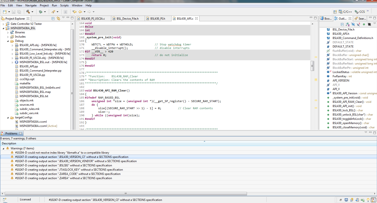
What all things need to modified to achieve this. I am using the 5438A experimenter board for this customization. As there is a USB to UART bridge on board already available. I need to modify the init sequence of peripheral. But when i try to build a project using all the necessary files I get build warnings specially related to "Flash not enough". What all things need to be modified in the linker cmd file as I am using CCS 5.2.
Regards,
Harshit
Hi harshit,
It sounds like you just want to do a software entry of the BSL from your main application - I'm guessing that in your main application, you use UART and when you receive a particular command you want the MSP430 to jump to the BSL? I think you should be able to do this without necessarily writing a whole new BSL - you might want to take a look at this forum post: http://e2e.ti.com/support/microcontrollers/msp430/f/166/p/244660/855616.aspx#855616.
Basically, in your main application code you should be able to define whatever UART command you want to trigger the BSL to start, then when you receive that command your code should disable interrupts and then jump to 0x1000. This will pass control over to the BSL. In this case, I don't think you'll have to modify the BSL that comes pre-loaded in the part. Note: it is important to disable interrupts before jumpint to 0x1000 to start the BSL because otherwise if an interrupt comes in while the BSL is running it will interfere - I think it will actually jump you out of the BSL in that case, causing issues.
Hope this helps!
-Katie
You can replace the BSL by your own. Part of the BSL is a funciton that checks whether the BSL is to be started or not. In your case, this function may always return yes instead of checking for the entry sequence bit, and the BSL itself can then wait for a timout before it gives control to the application. Still, a hard reset (RST pin) or power cycle will be required to enter the BSL (else the boot code won't test for BSL at all)harshit said:Can this be eliminated. I want to use the UART peripheral to invoke the BSL instead of the entry sequence by using JTAG pins.
HI Katie..
Thanks for your inputs. It has helped in proceeding further. I have still few queries like as follows:-
Katie Enderle said:Basically, in your main application code you should be able to define whatever UART command you want to trigger the BSL to start, then when you receive that command your code should disable interrupts and then jump to 0x1000.
So basically I need to modify the UART based BSL and add my own UART pins. Inside my application code i need to check for BSL entry..like
main()
init_bsl()
{
while(1)
{
check_UART_BSL_command();
.
.
.
}
}
But since I would be modifying the BSL to use UART as per my requirements. I might need to erase the preloaded BSl. So i need to use elptronic to load the BSL first using JTAG once at production and later on from UART right????
Is it required to use assembly here as I need to jump to BSL location??. I tried to build the basic code for initial testing to understand but i get linker errors. I am using the 5438A experimenter board to test the existing code.
I am hereby attaching my project and snapshots.. I am using CC5.2
Regards,
Harshit8468.Proj_bsl.rar
The F5438A BSL already uses a timer-based UART implementation. However, if you are already using the hardware UART in your application and need to use the same pins/UART module for the BSL, then yes, you will have to modify the BSL and load that (in particular becaue you will probably want to use your USCI module and the pre-loaded BSL uses a timer UART I believe).
There is an example PI (peripheral interface) file for using the hardware USCIA module included in the SLAA450 download that you should be able to use or modify to use the correct USCI module and pins to match the one you are using in your application.
1. Take the CCS F5438A project found in SLAA450/Custom_BSL_Zip_File/5xx_6xx_Example_BSL_Source and import it into CCS.
2. Remove the BSL430_PI_TA.c. Replace it with the BSL430_PI_USCIA.c file from SLAA450/Customer_BSL_Zip_File/5xx_6xx_BSL_Source/Peripheral_Interfaces/USCIA_UART/BSL430_PI_USCIA.c
3. in BSL_Device_File.h add this line: #define USCI_PORT_SEL P3SEL. Note that this is for using UCA0RXD and UCA0TXD pins P3.4 and P3.5 - you need to also change the line in the PI_USCIA file to set BIT4 + BIT5 instead of BIT5 + BIT6. If you want to use a different USCI module you'll need to change this and change the BSL430_PI_USCIA.c file accordingly.
4. You'll have to make some modifications to the BSL430_PI_USCIA.c file to get it to build in CCS. Remove the __no_init from in front of some variables, and get rid of the statements like #pragma required=BSL430_PI_Version that throw errors.
5. At this point when you build you'll probably get the errors like you do in the image you posted above - you need to set the Optimization for the compiler so that the code will fit in the BSL area of memory. Go to Project > Properties. In this dialogue you are going to set several settings.
Now when you click OK, you should be able to build and then load the BSL into your F5438A (note that in debug it will appear like there's no source - this is because it's running out of the BSL area and there is no main - this is normal behavior).
Now all you need to do from your main application to pass control to the BSL (after you've met whatever criteriayou decide to define that means you should go to the BSL) is to do this:
1. disable interrupts - you can do this with "bic_SR_register(GIE);"
2. jump to 0x1000. This line of C code will do it: "
((void (*)())0x1000)(); // This sends execution to the BSL. When execution
// returns to the user app, it will be via the reset
// vector, meaning execution will re-start.
I hope this helps get you up and running - modifying the BSL can be a tricky thing to do.
Regards,
Katie
HI Katie,
Thanks for the guidance. This resulted in a clean build, now I only have a ULP advisor warnings.
Yes its tricky to modify a BSL code.
I have few queries in getting started up the basic BSL before modifying it. I downloaded the example project by modifying the UART portions as per experimenter board. One thing I found that after running the code, the code remains blocked inside recive byte() function, I tried running the basic scripter.exe to send commands it shows me fail always. I tried hard but couldnt succeed. The document says to send a sync byte, but is that need to send manually or the scripter application wil handle it.How to test the basic example code if its working fine. Since the example code itself contains a main routine where will my main routine start of. Currently I was planning to put some piece of code inside receive byte function to invoke the BSL but I am not able to kickstart the basic example BSL code.
What specific changes needs to be made to the linker cmd file i replaced the cmd file in my new project with the one in example folder.
Thanks and Regards,
Harshit Jain
Hi Harshit,
I'm a little unclear about what you are doing in your last post. Are you using the MSP-EXP430F5438 experimenter board as your hardware?
To start with, you should test your BSL modifications before adding in the "software entry" in your main application or anything. You should be able to just load your modified BSL into your part, then use the BSL scripter to communicate with it using a Launchpad as your interface (see www.ti.com/lit/pdf/slaa535 ) - this test will be using the normal hardware entry sequence, but the launchpad code in slaa535 takes care of this for you. Make sure to connect the correct pins for the UART that you are using in your modified BSL.
After you have verified that this is working, you can start working on the "software entry" part of this project. For this, you can just take your main application code, where you'll have put some command that when you receive it you will jump to BSL by jumping to 0x1000 as we discussed above. You can just program this into your part and your BSL will still be in there (by default in CCS BSL memory won't be erased, so you don't have to worry about this). Then you can just run that code, send the UART command that you defined to jump to the BSL, and then start communicating with the BSL over UART as described in www.ti.com/lit/pdf/slau319 and in some other forum posts.
Regards,
Katie
Hi Katie..
Yes I am using the experimenter board to test the BSL
Katie Enderle said:To start with, you should test your BSL modifications before adding in the "software entry" in your main application or anything. You should be able to just load your modified BSL into your part, then use the BSL scripter to communicate with it using a Launchpad as your interface (see www.ti.com/lit/pdf/slaa535 ) - this test will be using the normal hardware entry sequence, but the launchpad code in slaa535 takes care of this for you. Make sure to connect the correct pins for the UART that you are using in your modified BSL.
As per above comment. I am not using launchpad as of now to test the example BSL code. Is it needed to test the basic software. Can I not test it without launchpad. Also since I was testing the BSL I had clicked on the options as suggested by u to erase"flash, information and protected memory" so i thnk the basic BSL has been erased by CCS whenever I try to download the example BSL code.
Even if later on I make a software BSL entry will the same BSL scripter work or even that needs a modification???
Well I would like to explain my current scenario..
I am not using launchpad for entry. I am just flashed the BSL example code with modifications in USCi _PI for the UART pins P5.6 and P5.7 (as these are connected to USB to serial converter in experimenter board). After running the code, I tried running the scripter with example script files for 5XX series and found that the commands always returned error. My aim was to get rid of the hardware entry sequence to enter into BSL mode. I thought that I could test the example code straightaway, but i could see the debugger is blocked i the receive byte code checking for some sync byte.
Thanks and Regards,
Harshit Jain
Hi Harshit,
The reason I recommend using the launchpad interface from the app note slaa535 and doing the entry sequence first is that it will let you get used to using the BSL and how the BSL works before you start making all of your modifications, as well as letting you test your steps along the way.
A few notes:
UCA1CTL0 |= UCPEN+UCPAR; // even parity
to:
UCA1CTL0 &= ~UCPEN; //none parity
initializeCommPort(comPort,1);
to:
initializeCommPort(comPort,0); //none parity
Note that you don't have to use the BSL scripter if you don't want to - the BSL interface is just UART and you can just send the commands over UART. You can make your own code to do this or take some code from the wiki: http://processors.wiki.ti.com/index.php/BSL_(MSP430)#BSL_Software But I tested the modifications with just a modified version of the scripter that I had set to use None parity as I described above.
After all these changes, you could either use the Launchpad to do the BSL entry sequence on RST and TEST or do it by hand or some other way. The sequence is described in SLAU319. This is just to test you made all the BSL changes correctly.
If all is working, now you can just create a completely new project that contains JUST your application code (not the BSL). In this project you will select to only erase and download main memory and do not check to include BSL memory in the erase. In this project is where you'll put your main application code, and your code to receive a UART command and then decide whether to jump to 0x1000 to start the BSL. After you send that command over UART, you would be able to start sending BSL commands (you may have to insert a small delay in between for the BSL to initialize).
I hope this makes things a little bit clearer.
Regards,
Katie
Hi Katie..
Thanks a lot ..things are getting clearer. But still not able to communicate with BSL after making the changes in PI code for no parity. I could see a function call in BSL_IO_UART.c scrpiter source code
/*******************************************************************************
*Function: initialize_BSL
*Description: Initializes the COM port and invokes the BSL.
*Parameters:
* char* comPort a string for the COM port ie "COM1"
*Returns:
* none
*******************************************************************************/
void UART_initialize_BSL_5438(unsigned char* comPort)
{
initializeCommPort(comPort,0);
invokeBSL();
}
the above function gets called when we specify the command in script.txt file as "MODE 543x_family COM20" due to which i concluded that there is no need to rebuild the scripter source code...pls correct me..???
Also I tried to build the scripter code using visual studio 2010 it gave me erorrs for a file related to usbhid not able to open hidsdi.h file. I was not able to fix this.
Well I have written a application project as below to make a software BSL entry
/*
* main.c
*/
#include "msp430x54xA.h"
#include "intrinsics.h"
void main(void)
{
unsigned char chk_inp_bsl = 0;
WDTCTL = WDTPW + WDTHOLD; // Stop watchdog timer
P1DIR |= BIT0 + BIT1; //P1.0 and P1.1 as output
P1OUT = 0xFF;
while(1)
{
chk_inp_bsl = P2IN & BIT6;
if(chk_inp_bsl == 0 )
{
P1OUT = BIT1;
_bic_SR_register(GIE);
((void (*)())0x1000)(); //jump to BSL
}
}
} which is working in the experimenter board logicaaly if i press the S1 switch. But when I run the scripter the commnds does not execute.
Also I had a doubt since I wuld not be using a hrdware entry sequence then whether this condition will ever be met in BSL_Low_level_init.asm file in BSL_Protect routine..
BSL_REQ_JTAG_OPEN .equ 0x0001 ;Return Value for BSLUNLOCK Function to open JTAG
BSL_REQ_APP_CALL .equ 0x0002 ;Return Value for BSLUNLOCK Function to Call BSL again
BSL_Protect
CLR RET_low ;lock (keep JTAGLOCK_KEY state)
BIC #SYSBSLPE+SYSBSLSIZE0+SYSBSLSIZE1 , &SYSBSLC ; protects BSL
;BIC #BSL_REQ_JTAG_OPEN, RET_low ;lock (keep JTAGLOCK_KEY state)
;BIS #BSL_REQ_JTAG_OPEN, RET_low ;make sure it remains open for debugging
bit #SYSBSLIND,&SYSCTL ;check for BSL start request (I have doubt here whether this will happen at alll in my case, pls suggest if modifications needed)
jz BCC2BSL
BIS.W #BSL_REQ_APP_CALL, RET_low
BCC2BSL RETA
I am following ur inputs closely but since I do not have a launchpad I m following my application code as I have mentioned above. I thnk so I am close. I have not modified the linker commnd in basic BSL scripter code.
Let me know if u have that file included in ur local directory for visual studio project.
Thanks once again for such great valuable inputs... eagerly waiting for ur reply....
Meanwhile I shall try without using a bslscripter to isolate the issue....
Thanks and Regards,
harshit
Hi harshit,
The function you are referencing is for an MSP430F5438 non-A device. If you are using MSP430F5438A, then you should not use MODE 543x_family - that specifies that you have a non-A device. THis will not work on an MSP430F5438A because in addition to not having parity the BSL in the F5438 non-A has a shorter BSL password and some other differences. So really you need to change the other UART_initialize_BSL() function to not use parity. I too was missing the hidsdi.h file in my install - so I just took out all of the code for USB BSLs in my modified scripter (since I really only needed it to support this particular modified BSL).
I've gone ahead and attached this modified version of the scripter to help: 4604.BSL_Scripter_no_parity.zip This zip file includes the modified version of the scripter and the script I used to test it - just in command line navigate to the directory and put "BSL_Scripter_no_parity.exe script.txt". The script loads msp430x54xA_1.txt, which is code to blink the LED on P1.0 - if the BSL correctly loads the code, you will see the LED1 on the experimenter board toggling after it runs.
I also tested doing the software entry as you did, with these two lines of code:
_bic_SR_register(GIE);
((void (*)())0x1000)(); //jump to BSL
This worked correctly when I tested it - after this jump occurs you should be able to run the no parity version of the scripter that I attached and it should be successful.
harshit said:Also I had a doubt since I wuld not be using a hrdware entry sequence then whether this condition will ever be met in BSL_Low_level_init.asm file in BSL_Protect routine..
By jumping to 0x1000 you actually skip past that code and go straight to the actual BSL entry. So this is not an issue. The beauty of still having that code there is that if you really needed to, you could still use the hardware entry sequence to get into the BSL (like if your software had been changed or the part had been mass erased or incorrectly programmed because it got unplugged in the middle of the BSL so you couldn't get it to execute the software entry). It's your insurance basically, and it doesn't interfere with your software entry so it is good to leave it in.
Regards,
Katie
A few more tips from my testing that I meant to include:
Regards,
Katie
Hi Katie..
Thanks a ton... finally I could test the modified BSL code using ur scripter file. Watching the blinking LED was such a pleasure. Now I am left with invoking BSL using a command from UART.
Thanks once again for the valuable support.
Regards,
Harshit
Hi Katie,
I also want to create a custom BSL based on MSP430F5438A which directly jump to 0x1000 into running the BSL from application code without TEST and RST pin. I am using a third party BSL interface and I have successfully run and tested the preloaded BSL via TEST, RST, P1.1 (TX) and P1.2 (RX) which are the default Timer_A UART in the BSL by using BSL_scripter. Does it also means that my interface support even parity since that is the default setting? So there will not be any problem in the interface right?
Just like you mentioned before, I imported the example BSL project from the SLAA450\Custom_BSL_Zip_File\5xx_6xx_Example_BSL_Source\CCS_v4.2.0_BSL-5438A, then I change some compiler setting and successfully build and load the program into my chip. The BSL also run correctly using the same interface. I also do some comparison between the code in the BSL CCS project and the one coming from IAR BSL example project, both are the same just in different platform.
The next thing I did is to remove the BSL430_PI_TA from the CCS_v4.2.0_BSL-5438A and replace it with BSL430_PI_USCIA which is inside SLAA450\Custom_BSL_Zip_File\5xx_6xx_BSL_Source\Peripheral_Interfaces\USCIA_UART.
Also like what you mentioned in the forum, I did some modification:
1) I add #define USCI_PORT_SEL P3SEL in the BSL_Device_File.h but I still get this error:
I then add the #define USCI_PORT_SEL P3SEL too in the BSL_PI_USCIA.c, then only the error is eliminated. The #define in the BSL_Device_File.h should have work, but I don’t know why.
2) Since I also want to configure the UART port using P3.4 and P3.5, so I just need to change BIT4+BIT5 since the default is already UCA0:
3) Next, I remove all the __no_init as well as the #pragma required=BSL430_PI_Version , and also change all the setting liked mentioned in the forum, then the project built successfully. I managed to load the program into F5438A.
4) So before dealing with the software entry, I retry the custom BSL via the previous interface using BSL scripter. This time, I change the TX pin on the interface to P3.4 and and RX pin to P3.5 and run the scripter. I am using the same script.txt which is as follow:
MODE 5xx COM1
DELAY 1000
MASS_ERASE
RX_PASSWORD BSLPassword.txt
TX_BSL_VERSION
RX_DATA_BLOCK test.txt
DELAY 100000
Unfortunately, the process fail once MASS_ERASE begin. I have also try modification in the IAR BSL example project using the same PI_USCIA.c, but still the same result.
So can you please give me any hint? Thank You.
Regards,
michaelng
Hello,
I'm also using MSP-EXP430F5438A and I've made the steps that Katie said and I managed to compile BSL example, and customize it to work with UCA1 on port 5 pins 6 and 7. At compilation I receive some warnings and I don't know what exactly they means:
#10247-D creating output section ".JTAGLOCK_KEY" without a SECTIONS specification MSP430F5438A_BSL
#10247-D creating output section ".BSLSIG" without a SECTIONS specification MSP430F5438A_BSL
#10247-D creating output section ".BSL430_VERSION_VENDOR" without a SECTIONS specification MSP430F5438A_BSL
#10247-D creating output section ".BSL430_VERSION_CI" without a SECTIONS specification MSP430F5438A_BSL
#10204-D could not resolve index library "libmath.a" to a compatible library MSP430F5438A_BSL
#10247-D creating output section ".ZAREA_CODE" without a SECTIONS specification MSP430F5438A_BSL
#10247-D creating output section ".ZAREA" without a SECTIONS specification MSP430F5438A_BSL
#10247-D creating output section ".BSL430_VERSION_API" without a SECTIONS specification MSP430F5438A_BSL
And when I run the code the CCS Debugger is starting and is loading the program in memory and after that is throwing an error "Load program error" with the following mesaage: "MSP430F5438A_BSL.out: a data verification error occurred, file load failed".
My problem is that I think I erased the old default BSL with the new one which is not working, because when I point my program to 0x1000 to enter in BSL the only thing it does is to restart the program again.
And I think the problems that I have are from project setup and compiling link etc. I use CCS 5.5 and the compiler version is 4.2.3
Does anybody knows how can I get rid of those warnings? and hopefully after that my custom BSL will work.
Thank you,
Claudiu
Hi Claudiu,
I just tried this with the latest SLAA450 download and CCSv5.5 and I did not have any issues and did not get the warnings that you did. The only way I was able to reproduce your issue was if I used the default MSP430F5438A linker file instead of the customized linker file for the BSL. Make sure that you are using the linker file that comes in the SLAA450 download in the folder at SLAA450/5xx_6xx_Example_BSL_Source/CCS_v5.5.0_BSL-5438A/lnk_msp430f5418a.cmd.
This may have the same name as the linker file you already have, but if you check the contents you should see the linker file defines all of these things like .ZAREA_CODE and .JTAGLOCK_KEY etc. I think this is your issue. I've also attached this customized linker file here: 2110.lnk_msp430f5418a.cmd
Regards,
Katie
P.S. Please also note for future visitors to this thread, that the latest SLAA450 download has an updated version of the CCS example BSL that has now been built for CCSv5.5. This makes the process easier and less steps than my earlier post, as it will import and build fine in CCSv5.5. The only changes you have to make are related to switching the PI layer out, since the USCIA PI code is written for IAR - this is still fewer steps than before.
Besides the source code, the BSL project also requires a modified linker script.
The compiler tells the linker to place the different code parts in specific memory locations, but the linker needs to know where these are. In a normal MSP project, the BSL memory area isn’t included into the linker memory map.
Besides this, your code seems to require the precompiled libmath library, but there is no proper version of it available for the code and memory model you use (or not at all). I don’t know why libmath is required at all. The BSL needs to be small, using library functions isn’t a good idea.
It looks like you've posted in this other new thread, I'll answer there: http://e2e.ti.com/support/microcontrollers/msp430/f/166/t/394095
old_cow_yellow said:This may be a red herring.
If you succeeded in get rid of the entry sequence and rely only on main() to invoke BSL, what do you do if main() has a bug and crashes? (That, in my opinion, is one of the moments you need to use BSL.)
That is a really excellent point. It is one reason why, even if you use the jump to 0x1000 invocation method to call the BSL from inside your main program, it is best to keep the low_level_init.asm present and relatively unaltered, at least such that the BSL can also still enter from the TEST/RST sequence method. That way you can still get into the device even on product returns or something. Providing TEST/RST and BSL TX/RX on test points I have seen save more than one person's project before. For example if parts are mis-programmed at the contract manufacturer and cannot be accessed via JTAG anymore or don't correctly do BSL software entry, having BSL connections available on test points and having the hardware invocation still be an option lets you re-program in that case, meaning less re-work.
-Katie
Hi Katie,
Thank you for your reply, I will have a try.
By the way, I think you guys are really kind because I rarely got reply in TI's China community, lol.
Thank you again,
Wang
Hi Katie,
I have read this whole supporting page. Before further operation, I just want to connect my MSP430F5438a board to PC using an USB-UART module. Then I modified the main application by adding "((void (*)())0x1000)(); " to make sure it can enter BSL mode when power on. Then I use the software provided by TI -BSL_Scripter.exe - trying to download a simple test program to my chip. So I tape the "MODE 5xx COM4" into the window, but it just got return that 5xx is invalid. So I think the connection is failed.My question is what module should I use to connect MSP430F5438a board to PC? I'm pretty sure I have connect the correct pin by referring the datasheet of the msp430f5438a. Is it possible that I can just use an USB-UART module to realize downloading new program into my board?
Thank you very much and I hope I can get some useful information.
Regards,
Wang
Hi Katie,
Thank you for your really fast reply, now I have just received the MSP-EXP430G2 LaunchPad, I have put the script.txt file in the same directory as scripter.exe. Hopefully, I can achieve my goal this time.
Wang
Hello Wang,
I read through your process and realized that I also had the same problem. Are you running the BSL_Scripter.exe by double clicking, or by entering it in the command line? If you don't pass it through the command line, the program will not execute. If you hold Shift and right click in the folder containing the script and the BSL_Scripter it will open a command window in that directory.
To save myself some time, I wrote a short batch script that runs the process for me. You may be interested in the same. Best of luck with your endeavors.
-Ivan
Hi Ivan,
Now i have realized this error, i changed my way of running that exe file, but still, i have some problems. i will try hard to work it out this weekend.
Anyway, thank you for your advice.
Wang
Hi Katie,
Thanks to your great help, I have downloaded demo program into my 5438A board by using both BSL entry timing sequence and the sentence:((void (*)())0x1000)();
Now I want to change the original BSL program to use a different USCI module :p3.4 and p3.5. So I modified the project (CCS_v5.5.0_BSL-5438A) according to this thread step by step, but when I build the project, there are some errors, in case of potential error that is made by my modification, I build the original project again, but there still have some errors as following :
"../lnk_msp430f5418a.cmd", line 152: error #10099-D: program will not fit into available memory. placement with alignment fails for section ".BSL430_VERSION_CI" size 0x1 . Available memory ranges:
BSL430_VERSION_CI size: 0x1 unused: 0x1 max hole: 0x1
"../lnk_msp430f5418a.cmd", line 154: error #10099-D: program will not fit into available memory. placement with alignment fails for section ".BSL430_VERSION_PI" size 0x1 . Available memory ranges:
BSL430_VERSION_PI size: 0x1 unused: 0x1 max hole: 0x1
error #10010: errors encountered during linking; "MSP430F5438A_BSL.out" not built
>> Compilation failure
gmake: *** [MSP430F5438A_BSL.out] Error 1
gmake: Target `all' not remade because of errors.
**** Build Finished ****
The errors shown above are identical to my modified project. I have noticed that the cmd file in the project is named as lnk_msp430f5418a.cmd, so I wonder if this file leads to all the errors.
Hopefully, you can give me some advice.
Thanks,
Wang
Hi Wang,
To me those error messages look like the linker is having problems placing the BSL version information. However, this version information is not strictly necessary(though it can be useful), so you could try commenting out the lines that set these to see if it helps. The BSL is unfortunately pretty tight in the 2kB of BSL Flash, so you can run into problems when making modifications if the program doesn't compile small enough.
-Katie
Hi Katie,
Thank you for you really fast reply. I have commented out these lines to see if this time I can build successfully, but this time, another error happened (actually it also happened last time, but I didn't noticed it):
**** Build of configuration Debug for project MSP430F5438A_BSL ****
"D:\\wzl\\software\\TI\\CCSV5\\ccsv5\\utils\\bin\\gmake" -k all
'Building target: MSP430F5438A_BSL.out'
'Invoking: MSP430 Linker'
"D:/wzl/software/TI/CCSV5/ccsv5/tools/compiler/msp430_4.1.2/bin/cl430" -vmspx --abi=coffabi -O4 --opt_for_speed=0 -g --advice:power="all" --define=__MSP430F5418A__ --diag_warning=225 --display_error_number --diag_wrap=off --silicon_errata=CPU21 --silicon_errata=CPU22 --silicon_errata=CPU23 --silicon_errata=CPU40 --single_inline --remove_hooks_when_inlining --printf_support=minimal -z --stack_size=160 -m"MSP430F5438A_BSL.map" --heap_size=160 --use_hw_mpy=F5 -i"D:/wzl/software/TI/CCSV5/ccsv5/ccs_base/msp430/include" -i"D:/wzl/software/TI/CCSV5/ccsv5/tools/compiler/msp430_4.1.2/lib" -i"D:/wzl/software/TI/CCSV5/ccsv5/tools/compiler/msp430_4.1.2/include" -i"D:/wzl/software/TI/CCSV5/ccsv5/ccs_base/msp430/lib" --reread_libs --warn_sections --display_error_number --diag_wrap=off --xml_link_info="MSP430F5438A_BSL_linkInfo.xml" --rom_model -o "MSP430F5438A_BSL.out" "./BSL430_PI_TA.obj" "./BSL430_Low_Level_Init.obj" "./BSL430_Command_Interpreter.obj" "./BSL430_API.obj" -l"libmath.a" -l"libc.a" "../lnk_msp430f5418a.cmd"
<Linking>
remark #10371-D: (ULP 1.1) Detected no uses of low power mode state changes using LPMx or _bis_SR_register() or __low_power_mode_x() in this project.
error #10008-D: cannot find file "libmath.a"
remark #10372-D: (ULP 4.1) Detected uninitialized Port A in this project. Recommend initializing all unused ports to eliminate wasted current consumption on unused pins.
remark #10372-D: (ULP 4.1) Detected uninitialized Port B in this project. Recommend initializing all unused ports to eliminate wasted current consumption on unused pins.
remark #10372-D: (ULP 4.1) Detected uninitialized Port C in this project. Recommend initializing all unused ports to eliminate wasted current consumption on unused pins.
remark #10372-D: (ULP 4.1) Detected uninitialized Port D in this project. Recommend initializing all unused ports to eliminate wasted current consumption on unused pins.
remark #10372-D: (ULP 4.1) Detected uninitialized Port E in this project. Recommend initializing all unused ports to eliminate wasted current consumption on unused pins.
remark #10372-D: (ULP 4.1) Detected uninitialized Port F in this project. Recommend initializing all unused ports to eliminate wasted current consumption on unused pins.
"../lnk_msp430f5418a.cmd", line 222: warning #10374-D: Interrupt vector "RTC" does not have an interrupt handler routine.
>> Compilation failure
"../lnk_msp430f5418a.cmd", line 223: warning #10374-D: Interrupt vector "PORT2" does not have an interrupt handler routine.
"../lnk_msp430f5418a.cmd", line 226: warning #10374-D: Interrupt vector "USCI_B1" does not have an interrupt handler routine.
"../lnk_msp430f5418a.cmd", line 227: warning #10374-D: Interrupt vector "USCI_A1" does not have an interrupt handler routine.
"../lnk_msp430f5418a.cmd", line 228: warning #10374-D: Interrupt vector "PORT1" does not have an interrupt handler routine.
"../lnk_msp430f5418a.cmd", line 229: warning #10374-D: Interrupt vector "TIMER1_A1" does not have an interrupt handler routine.
"../lnk_msp430f5418a.cmd", line 230: warning #10374-D: Interrupt vector "TIMER1_A0" does not have an interrupt handler routine.
"../lnk_msp430f5418a.cmd", line 231: warning #10374-D: Interrupt vector "DMA" does not have an interrupt handler routine.
"../lnk_msp430f5418a.cmd", line 234: warning #10374-D: Interrupt vector "TIMER0_A1" does not have an interrupt handler routine.
"../lnk_msp430f5418a.cmd", line 235: warning #10374-D: Interrupt vector "TIMER0_A0" does not have an interrupt handler routine.
"../lnk_msp430f5418a.cmd", line 236: warning #10374-D: Interrupt vector "ADC12" does not have an interrupt handler routine.
"../lnk_msp430f5418a.cmd", line 237: warning #10374-D: Interrupt vector "USCI_B0" does not have an interrupt handler routine.
"../lnk_msp430f5418a.cmd", line 238: warning #10374-D: Interrupt vector "USCI_A0" does not have an interrupt handler routine.
"../lnk_msp430f5418a.cmd", line 239: warning #10374-D: Interrupt vector "WDT" does not have an interrupt handler routine.
"../lnk_msp430f5418a.cmd", line 240: warning #10374-D: Interrupt vector "TIMER0_B1" does not have an interrupt handler routine.
"../lnk_msp430f5418a.cmd", line 241: warning #10374-D: Interrupt vector "TIMER0_B0" does not have an interrupt handler routine.
"../lnk_msp430f5418a.cmd", line 242: warning #10374-D: Interrupt vector "UNMI" does not have an interrupt handler routine.
"../lnk_msp430f5418a.cmd", line 243: warning #10374-D: Interrupt vector "SYSNMI" does not have an interrupt handler routine.
warning #10247-D: creating output section ".BSL430_VERSION_CI" without a SECTIONS specification
warning #10247-D: creating output section ".BSL430_VERSION_PI" without a SECTIONS specification
error #10010: errors encountered during linking; "MSP430F5438A_BSL.out" not built
gmake: *** [MSP430F5438A_BSL.out] Error 1
gmake: Target `all' not remade because of errors.
**** Build Finished ****
So you can see the result, there is only one error now, but still a lot of warnings, this is the build result of original program .
Because the name of cmd file in this project is lnk_msp430f5418a.cmd, so I wonder if there is a msp430f5438a version.
The error shown above is said cannot find file "libmath.a". So I want to know where can I find this file.
Another question I have is, in the project that is provided by TI, the ccxml file is MSP430F5418A.ccxml, I wonder if I should change it to fit 5438A board.
Thank you very much,
Wang
Hi Katie,
I have found libmath.a file and build successfully. But I have failed to download it into my 5438a board, I will try my best to find the reason. I also pick "Create Flash image TI-TXT" so I have a txt file after build. As I didn't download the new BSL program into my 5438a board successfully, I tried to download this txt file into my board, but again, it failed. The download software said subscript out of range, so I wonder if I really can load in a production environment.
I still want to download the txt file into my 5438a board. This time, I use the bsl_scripter.exe, although it sounds somehow weird to download new bsl program into 5438A board by using bsl mode, I have a try again, and failed again...the problem is as following:
So I think there are two possibilities for this failure:1.The MSP430F5438A_BSL.txt file is too big;2.This file can't been downloaded into 5438a board because when in BSL mode, it can't make change to BSL part.
I hope you can give me some information...
Thanks,
Wang
Hi Wang,
Are you working from the F5438A BSL example project? You need to have your project settings set so that you can load code into BSL memory - the BSL memory is protected from erase/write normally, so you have to set this in your CCS project. Go to Project > Properties then under Debug > MSP430 Properties scroll down to Erase Options and check "Allow read/write/erase access to BSL Memory". You may also need to select Erase main, information and protected information memory.
Also trying to load a new BSL via the scripter won't work, because if you had successfully erased the BSL memory you'd have had no BSL inside the MSP anymore to do the loading - so it would fail.
Regards,
Katie
Hi Katie,
Thanks for your help, now I at least know that it's impossible to download a new BSL via bsl_scripter.exe. By the way, as I have choose the "Create Flash image TI-TXT" under Project->Properties->Build Steps tab, a txt file is generated by CCS is about 7kB, and because BSL flash is only 2kB, so I wonder if this means this txt file can't be loaded into 5438A.
Another question is, under Project->Properties-> General->Main tab, I saw the Variant is MSP430F5418A, should I change this?
Thanks,
Wang
Hi Katie,
Thank you for your reply, now I know I use the wrong method to get the size of TXT file. Actually I managed to build my code in CCS successfully, but as I don't have a device to load the code from CCS to 5438A board directly, so I just try to load the TXT file into the board. Unfortunately, as you said, I can't load BSL program into 5438A when it is in BSL mode. So now what can I do is just to wai tthe arrival of my MSP-FET430UIF device. After I receive this device, I think I can manage to load this new BSL program into 5438A by using JTAG.
Thank you again for you reply,
Wang
Hi Katie,
I tried to modify BSL program in 5438A when in BSL mode. Obviously, I can't modify BSL program when 5438a is in BSL mode and trying to load a txt file into 5438A (this txt file is generated by CCS which I once hope it can modify BSL program). Then my 5438A couldn't work correctly.
So I bought a new 5438A, and before I load new BSL program into it, I have test it can work correctly. So I load new BSL program using MSP-FET430UIF this time, for the first time I click debug button, there are some error shown like following:
after i click ignore button, CCS shows:
so i checked the MSP430F5418A.ccxml file under targetConfigs folder in CCS, i found that in board or device, msp430f5418A was chosen, then i think this could leads to problem because my target is 5438A, so i changed it to msp4305438A and clicked debug button again, this time, CCS shows me some information like blow:
I think this means CCS can't find 5438A board now?! And now i also can't manage 5438A board to get into BSL mode by using MSP-EXP430G2. So i don't know should i do next, now I just feel somehow depressed , and i wonder if i really can change BSL program.
can you please give me some advice?
Thank you very much!
Wang
Hi Wang,
When you clicked "ignore" on the first warning it should have worked just fine - the reason the project is set to F5418A is to be set to the variant of that device family with the smallest RAM space. This way it should work on any device in that F54xxA family.
Now the first error you get about file verification failed - I believe this is because you may not have the project debug settings set correctly to support erasing and programming into the BSL area. Please go to Project > Properties > Debug > MSP430 Properties. Under Download options, make sure to check Allow Read/Write/Erase access to BSL memory, and under Erase Options, select Erase main, information, and protected information memory. Now try again (if you set the project to F5438A it's going to use the default linker file for that part - but you need the project to use the modified F5418A linker file that came with the BSL project - so return this to original device settings please).
Hope that this helps you get your BSL to load.
user4215514 said:And now i also can't manage 5438A board to get into BSL mode by using MSP-EXP430G2. So i don't know should i do next, now I just feel somehow depressed , and i wonder if i really can change BSL program.
Are you using the SLAA535 www.ti.com/lit/pdf/slaa535 code on your Launchpad to do the BSL entry? Please also note that if you have the new MSP-FET tool (black tool rather than older grey tool) this also supports BSL mode with the BSL_Scripter software.
Regards,
Katie
Hi Katie,
Thanks for your reply and help for me many many times.
Before I download the new BSL program, I have set the settings as you said and checked not only once.
For your question that if I'm using SLAA535, I would say I use exactly this file and verified the correction of my new 5438A bsl by generating a bsl timing sequence using this MSP-EXP430G2, also, I added _bic_SR_register(GIE); and ((void (*)())0x1000)(); into my main function to see if the chip can enter BSL mode by software method, and it also succeeded.
So I guess the reason for failed to invoke BSL mode is that the BSL program have been somehow modified, but not what I want. Is this possible?
Thank you very much!
Wang
Hi Katie,
Sorry for I didn't describe my current issue clearly. Now I want to describe what I have done step by step, so maybe you can help me to find some error...
First, I bought a new 5438A board, before I load a new BSL program into it, I want to test if this chip can work correctly. So I managed to get 5438A into BSL mode by using MSP-EXP430G2, which can generate a BSL entry time sequence, then I use the bsl_scripter.exe to downloaded a new example program into the board successfully.
Second, I want to test if I can manage to get 5438A into BSL mode using a different way, that is, by adding following sentences into my main function in 5438A:
bic_SR_register(GIE);
((void (*)())0x1000)();
After a power-up on my board, I assume that it is now in BSL mode. So I use bsl_scripter.exe again and downloaded a new program into my 5438A board successfully.
At this point, I assume that there is no problem or error in my new board, and I can try to download a new BSL program into 5438A . My aim is to use the hardware USCIA module when 5438A is in BSL mode - pin 3.4 and pin 3.5. So I do the modification in CCS such as remove the BSL430_PI_TA.c and replace it with the BSL430_PI_USCIA.c file, add #define USCI_PORT_SEL P3SEL in BSL_Device_File.h, etc. After this, I changed the properties in CCS according to this post. Then I connected PC with 5438A board using MSP-FET430UIF. After that my problem happened.
Now my board can't enter BSL mode anymore even by using MSP-EXP430G2. I'm eager to know what can I do now.
Thank you very much.
Wang
Hi Wang,
Thanks for this information it is very helpful to explain your situation. I'm assuming you are using the MSP-TS430PZ5x100 board, not the MSP-EXP430F5438 experimenter board correct? The reason I'm asking is because if you are using the UART port on the MSP-EXP430F5438 then you will need to set your BSL scripter and BSL to not use parity (because it uses a TUSB chip on that UART port which is not set to support parity). I also think it might be set up to use a different baud rate.
This post earlier in the thread includes a link to a modified BSL Scripter that does none parity: https://e2e.ti.com/support/microcontrollers/msp430/f/166/p/246869/876141#876141 If you do this, I think you should not use the MSP-EXP430G2 for communicating with the board but use the UART connector on the experimenter board - this is because the MSP-EXP430G2 adds parity to the communication before sending to the target device, so it wouldn't work if you need this to be none-parity for your BSL.
Now, if you are using the MSP-TS430PZ5x100 board, then I would not modify the BSL to use different parity or anything (switch it back if you had changed that) - then you can use MSP-EXP430G2 for your communication with the BSL and the unmodified BSL Scripter.
Regards,
Katie
Hello Katie, I've done all the 5 steps you write and I have one problem and I think is I'm using conpiler version TI v4.2.1, when I download the software to my MSP430F5438A I get this error "Load Program Errror" "File: ..\Debug\MSP430F5438A_BSL.out: a data verification error occured, file load failed. I think the probleme is because I have those warnigs
Hello Katie is it wrong that when I debug the project MSP430F5438A_BSL it enters in debug mode and let me do debugging and jumps at main function in BSL430_Command_Interpreter.c ?
**Attention** This is a public forum