This thread has been locked.

If you have a related question, please click the "Ask a related question" button in the top right corner. The newly created question will be automatically linked to this question.

ADC with MSP430G2553

Other Parts Discussed in Thread: MSP430G2553, INA321

Hi everybody;
I’m a beginner; before starting this thread, I’ve read many others regarding ADC in this forum, but I’d like to have your comments about the circuit I’m working on.

1)      The microcontroller is the MSP430G2553 (in TSSOP package), decoupled with the “0,1μF + 10μF combo” capacitors.

2)      The supply voltage comes from an LDO (2.5V), properly decoupled.

3)      The source of the analog input is the output of an OpAmp; as written in its datasheet, “The output pins are low-impedance voltage sources”.

4)      I’ve placed a low-pass filter BEFORE the OpAmp, and I’ve properly decoupled the OpAmp. The VCC pin of the OpAmp is directly connected to a generic pin of the microcontroller, which turns ON the OpAmp when needed.

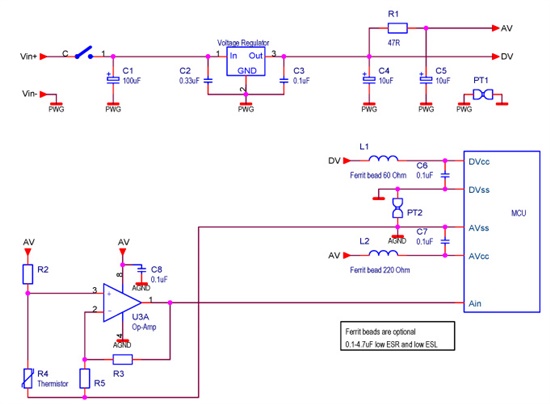
You can see the microcontroller + LDO in the picture below.
Question #1: in order to have a better ADC reading, would it be better using a different ground trace for the MCU and the LDO, like in the picture below?
However, with the scheme as shown in the first picture, I’m having very good results, until I don’t  do anything else than reading the ADC  value.
But if I try to do something else (even just starting a timer, or lighting a led), results begin to deteriorate.
I thought the problem was that I didn’t place a decoupling capacitor close to the pin that receives the analog signal, but as  Jens-Michael Gross wrote in this thread
The internal cap and its 1k series resistor is a low-pass filter. An external cap with the signal source impedance is a low-pass too. The lower one of the two defines the characteristic of the signal the ADC 'sees'.”
Considering that in my application the source impedance should be low, maybe that capacitor wouldn’t help.
So I begin to think that the problem is the fact that the MCU I’m using doesn’t have separate analog power pins (AVCC and AVSS). But the same MCU is available in QFN format, which has those pins.
Could it be the solution to my problem?
If so, should I use the following solution (Picture 3)?
I’ve placed a 10Ω resistor between AVCC and DVCC because I found it in many threads written by Jens-Michael Gross, and it makes sense. Considering that I’m using the analog supply voltage just for the ADC, maybe I could rise the value up to 100Ω.
Could it be the right solution?
Should I use the same AVSS ground line for the OpAmp?
Thanks in advance to everybody.
Marco
  • All your grounds (DVSS/AVSS) shall connect capacitor C1 at the output of LDO. So 1) is better than 2). Don't forget that C1 GND is ground "bar" for every ground - for signal sources you measure either.

    Marco2002 said:
    The VCC pin of the OpAmp is directly connected to a generic pin of the microcontroller, which turns ON the OpAmp when needed.

    You shall run more tests: power amp from AVCC/AVSS rails instead, run tests.

    You think about \decoupling strategies of AVCC, DVCC ... and ... DANG!! - connect amplifier to output pin that comes out of noisy uC digital fabric. If you care about clean analog supply you shall use small AVCC-connected p-fet switch instead, never power any analog parts out of (digital & noisy) pin.

  • Hi Ilmars,

    thank you very much for your precious advices, I'll make good use of them.

    Marco

  • Ilmars said:
    never power any analog parts out of (digital & noisy) pin.

    Well, OpAmps usually have a good supply ripple suppression (>80dB). So the DVCC noise on the MSP output pins won't have too much effect. Especially if you decouple the OpAmp supply with another cap.

    WHiel the AVCC conencted FET switch seems to be a good idea at first, it will introduce a variable current sink to AVcc and perhaps introduce ripple into AVcc, which will in turn influence the A/D conversion quality. Which way is better cannot be determined by general rules.

    BTW: Connection 3 is good, if the MSP has separate AVcc/AVss. Except for the GND point. It should be GND of C1 on the regulator output.

    In any case, 2.5V is not really much to power an OpAmp. These devices usually work best with lots of headroom between signal and the supply rails. (I don't say they won't work at all, but small supply range affects linearity, rise times etc.)

  • Maybe this might help;

  • Hi Jens-Michael.
    So, this is the correct configuration.
    Any other ground line will be connected to the capacitor C1 at the output of LDO.
    Jens-Michael Gross said:
    OpAmps usually have a good supply ripple suppression (>80dB). So the DVCC noise on the MSP output pins won't have too much effect. Especially if you decouple the OpAmp supply with another cap.
    The ripple suppression of the OpAmp I’m working with is 83dB, so it should be good enough.
    I’m decoupling the OpAmp with one bypass capacitor (0.1μF); I’ll add another, bigger one, in order to have a compound by-passing.
    Jens-Michael Gross said:
    In any case, 2.5V is not really much to power an OpAmp.
    The OpAmp has a supply voltage of 1.8V to 5.5V, and my circuit is powered by a 3V battery (LDO-regulated to 2.5V); I understand that it’s not the best voltage (for the OpAmp), but I can’t do otherwise.
    Jens-Michael Gross said:
    Which way is better cannot be determined by general rules.
    I’ll try both the solutions (OpAmp powered by a transistor VS. powered by a generic pin of the MCU), to see which one is more suitable for my project.
    Being pretty ignorant, I’d like to ask you one more information (it’s stupid, but I’m just a novice); when I power the OpAmp through a transistor, what solution is better, N-channel FET or P-channel FET? And with the OpAmp on the low-side of the transistor or on the high-side of the transistor? I’ve found different solutions on the internet, and I’ve not the competency needed to understand which one is the best (for my application).
    Hi Leo,
    thank you for the scheme you posted, I'll study it.
     Thank you again for sharing your experience.
    Marco
  • N-Channel FETs require a gate voltage above their drain voltage. So if you use one, you either have to put in into the negative supply of the OpAmp (bad thing, as the OpAmp is still powered but without GND) or to control its gate with a voltage higher than the positive supply. Difficult if MSP and OpAmp shall operate on the same 2.5V supply.

    P-Channel FETs require a gate voltage below their drain voltage to let a current flow. So you can put them into the positive supply of the OpAmp (between Vcc and OpAmp V+). The MSP must output an active high to keep the FET off. So either you put a pull-up on it (which causes an additional current when the MSP is pulling the gate down to activate the OpAmp) or it will be initially on until the MSP is pulling the gate high actively. Again your choice.

    Note that FETs are voltage controlled resistors (until saturation). So you'll have a resistor in the OpAmp supply. Check the FETs effective resistance for the given gate/drain voltage and source/drain voltage. It's not a straightforward lookup as most datasheets define the currents.

  • Jens-Michael, tank you again for answering to my question.

    Marco

  • Search the analogue site from TI for an Op-Amp with Shut-down (and for other analogue issues), can simplify your design. For example INA321.

  • Hi Leo,

    Great suggestion, I’m finding interesting alternatives to my OpAmp.
     
    Thank you again,
     
    Marco
  • Jens-Michael Gross said:
    never power any analog parts out of (digital & noisy) pin.

    Well, OpAmps usually have a good supply ripple suppression (>80dB). So the DVCC noise on the MSP output pins won't have too much effect. Especially if you decouple the OpAmp supply with another cap.[/quote]

    I said "analog parts", not OpAmps ;) Thing is that you cannot easily say "opamps have good supply ripple suppression - you will be fine" to unaware of ground noise, engineers. Especially if they decouple OpAmp but connect signal source ground to wrong place. Basically we shall repost whole book here to be absolutely correct about everything we say.

  • Ilmars said:
    I said "analog parts", not OpAmps

    Well, we were talking about an OpAmp all the time. (Which is an analog part anyway). For anything without supply voltage ripple rejection (digital parts have maximum ripple rejection), of course a supply without ripples should be used.

    Ilmars said:
    to unaware of ground noise, engineers.

    We already have a separate analog ground trace, so nobody was unaware. And the ripple discussion was about using the digital output voltage as supply, not about any ground noise.

    Ilmars said:
    Especially if they decouple OpAmp but connect signal source ground to wrong place.

    That's of course a faux-pas. :)

    Ilmars said:
    Basically we shall repost whole book here to be absolutely correct about everything we say.

    We're no politicians.:)
    But you're right, the level of experience of the different forum members is so widespread that it is difficult to say what to explain and where to make the cut.

  • Jens-Michael Gross said:
    you're right, the level of experience of the different forum members is so widespread that it is difficult to say what to explain and where to make the cut.

    Jens-Michael and Ilmars, you’re both soooooo right (especially, when talking about me).
    This is the main reason for which I always specify, at the beginning of what I write, that I’m a beginner: everybody feels free to tell me even the simplest things, without being afraid to write too much.
    Look at my first picture: I’m working with a single-layer PCB, and I know that a good approach is to use a ground star point. I thought that the correct point was the 0V of the battery, and I was really wrong: for what you both wrote, the star ground point is the  GND of C1 on the regulator output.
    It can be an unnecessary information for 99% of the users of this forum, but it’s greatly appreciated by me.
    So Ilmars, Jens-Michael and Leo, than you again.
  • Marco2002 said:
    for what you both wrote, the star ground point is the  GND of C1 on the regulator output.

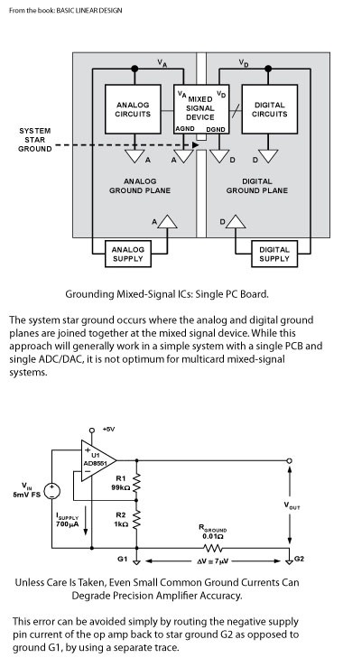
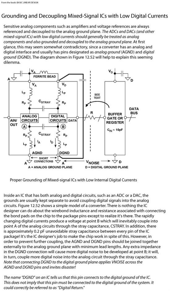
    I think you didn’t get the sense. Study this;

    It does not apply so well to MCU, they will give more digital noise and in this case I would connect DVss to Dgnd but keep the Star-Point between Agnd and Dgnd close to the MCU.

  • LEO, ARE YOU TRYING TO MAKE ME CRAZY????


    Seriously: as I wrote before, I’m working with a 1-layer PCB; so, I don’t have a digital ground plane, nor an analog ground plane.

    The best thing should be having a ground star point; it can’t be too near the MCU’s pins (I mean, between the MCU and the 4 decoupling capacitors), so I think that putting the star ground point at the GND of C1 on the regulator output is actually the correct way (maybe it’s not the perfect solution, but it’s fine, for a 1 layer PCB).

    This is what I understood, but if you have any comment (really everything), feel free to let me know.


    Thank you again for your extra-time.
    Marco

  • Marco2002 said:
    I’m working with a 1-layer PCB; so, I don’t have a digital ground plane, nor an analog ground plane.

    I missed that, but ground plane or not is not the issue, and in the information I give here you can replace Ground-Plane by Ground-Wire. Also using a ground-plane, inductors, resistors or capacitors doesn’t mean you solve your noise or spike problems, reverse they can make it more worst if not used on the proper way. I was trying to let you (and other) to realize there is noise and how and in which direction they are flowing and how to deal with it (taking it fully away is not always possible). Every design needs its own approach, there is no standard solution.

    A wire from MCU to a central point/capacitor and back to the MCU, is an air-coil and can easily start’s to oscillate and your problem will be bigger, a capacitor of 0.1uF does nothing against it or maybe even helps it to oscillate (only a series resistor of about 100R will stop oscillation). And to short spikes only a capacitor of 22nF or smaller will be effective, but realize in a poor design a capacitor is just partly absorbing the spike energy, a lot will be transferred to the other (ground) side and comes back.

    Look into the MCU, keep everything quiet as possible here, when connecting the ground’s together they may contain noise but inside the MCU they are not generating any potential. Look from the MCU (ADC) into the direction of your analogue source (Op-Amp) if both connections, ground and signal only drawing the current necessary for the signal, ground may contain noise but (nearly) the same noise will be on the signal wire (add capacitor in between) and will not influence the conversion result. Connecting the negative-return of the Op-Amp to the MCU Agnd point will then also not influence the result. Trying to absorb (not transferring to some other point) noise/spikes is one, the next is to deal with the remainder.

    Now your brains starts to boil!

  • Additionally;

    I have the idea that sometimes a 0.1uF decoupling capacitor is seen as a noise or spike absorber, but it isn’t. The function of the capacitor near an IC is to decouple the power-line from the IC, so that when the IC momentary needs an excessive amount of power (current) the capacitor can supply this need without lowering the supply rail, or in reverse for a supply source (LDO). It will not block noise from the IC to the power line, a ferrite bead will.

  • Leo Bosch said:
    Now your brains starts to boil!

    JAAAAA!!!!!!!!!!!!!!!

    Leo Bosch said:
    Every design needs its own approach, there is no standard solution.

    This is the scariest thing!
    This is what I’m going to do: I’ll use the “star grounding philosophy”, trying to connect every GND at the GND of C1 on the regulator output, and adding a capacitor between the Op-Amp ground and the signal wire.
    But it will be very difficult, because I’ll have to do everything while keeping my fingers crossed!!!
    Anyway, I have not enough knowledge to make a state-of-the-art circuit; but I hope that, with such a simple circuit, and with a 10 bit (NOT 12 bit) ADC, the result will be satisfying.
     
    Thank you again,
     
    Marco
  • For what I've seen, the ferrite bead could replace the 10 Ohm resistor in the scheme, between DVCC and AVCC. I'll try even that, I promise.

    Marco

  • Ferrite beads to block noise/spikes must be placed on the source side of the noise. From the LDO himself you don’t have to expect much noise or spikes so here it is useless, but at the LDO input side is a good place specially when +V comes from a SMPS. And on the source side, thus close to the +V point. A resistor is basically used as a equalizer, take away of voltage ripple. As big as possible but not that big that the voltage drop comes too big, 100R will fit.

  • Leo Bosch said:
    It will not block noise from the IC to the power line

    Well, partly. Most noise is rather an effect of the non-constant (clocked) current consumption of a device, with partly high transients.

    The blocking capacitor, as you correctly wrote, is to satisfy this momentary need of current locally.This causes the ripple current to only appear between device and capacitor.  Voltage drop due to the ripple current over a (non-zero impedance) supply line is reduced. You'll still have some ripple on the whole supply, as the capacitor will of course try to recharge. But as a result, the transients are much smaller and the ripple strength and frequency spectrum on the supply on the other side of the capacitor is significantly reduced.
    Most (if not all) of the noise you see on supply lines is an accumulated ripple caused by the various devices. And therefore the blocking capacitors are noise filters. However, tehy do not prevent noise form coming in, but rather from going out.
    So they have to be used where the noise is created, not where it has to be avoided.

    OTOH, a combination of a series resistor and a blocking capacitor (effectively a low-pass filter), where no noise is created (due to only very small and/or constant current flow) will indeed keep noise from coming in.  As it is recommended for AVcc.

  • In generally you are right but you are diffusing my point. What I want to focus on and tries to increasing the contrast in use between the different parts as capacitor, inductor, resistor etc. I have the feeling that many people thinks: Place a capacitor somewhere here and all my problems are solved, as I told they may even increase the problems. But of course it’s not that sharp as I explained, most of all parts consist of (acts as) an capacitor, resistor and an inductor even a copper trace must be seen as an (important) inductor. Always analyze your design and inventor potential problems and attack them on the source side.

    Of course a capacitor on IC side will absorb some noise/spikes but how much, well not much when 0.1uF, much better if 10nF or smaller but if you really expect and want to block noise use a (adequate) ferrite bead 99.9% guarantee.

  • Leo Bosch said:
    I have the feeling that many people thinks: Place a capacitor somewhere here and all my problems are solved

    Well, a capacitor alone won't make anything regarding noise. However, most people simply forget that traces have a resistance and are inductors too. So adding a capacitor forms a low-pass filter, which sometimes really helps. However, intentionally putting a series resistor too may greatly enhance the effect.

    However, you're right, mindlessly placing capacitors won't always help and may be even counter-productive.

    Leo Bosch said:
    well not much when 0.1uF, much better if 10nF or smaller

    Smaller = better? I don't think so - at least if both are of same technology. Usually the larger capacitance also has also smaller ESR. Of course an electrolytic cap is way less effective in suppressing noise than a ceramic one, despite of its larger capacitance. And even for ceramic ones there are different materials (NP0,XR5, XR7 etc.) But an 100nF XR5 ceramic is expected to be better than a 10nF XR5 ceramic.

    Leo Bosch said:
    f you really expect and want to block noise use a (adequate) ferrite bead 99.9% guarantee.

    Out switching power supply then is one of the remaining 0.1% :) The ferrite bead was of no use to suppress the HF switching noise. Changing the trace routing to a star-design around the central storage capacitor helped much more.

  • Jens-Michael Gross said:
    The ferrite bead was of no use to suppress the HF switching noise. Changing the trace routing to a star-design around the central storage capacitor helped much more

    I know my explanations are sometimes a little bit short, but I mend blocking noise coming from a source such as a MCU (and also placed close to the MCU). A star is more DC-leveling and not blocking noise unless the star-point is relative small to the trace size forming a V or angular cut, this will also block spikes. Sometimes the design needs more than one star-points for example: Power-GND (AUX)-> Digital-GND (MCU)-> Analogue-GND.

  • Leo Bosch said:
    A star is more DC-leveling and not blocking noise

    The noise we are talking about is more a high-frequency signal than real noise, so DC leveling and low-pass filtering will help.
    Real noise as it is generated by current passing through a resistor or p/n substrate of course cannot be filtered this way - any additional component will rather increase it.

    Well, as soon as you leave the rails of the quantized digital world, things start to get complicated :)

  • Leo Bosch said:
    Sometimes the design needs more than one star-points for example: Power-GND (AUX)-> Digital-GND (MCU)-> Analogue-GND.

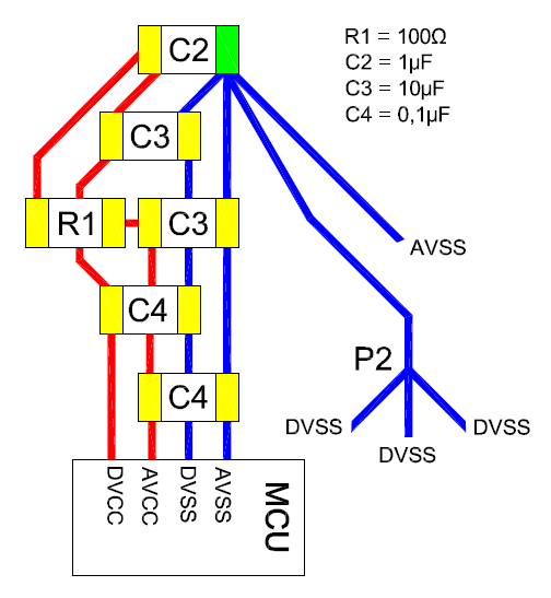
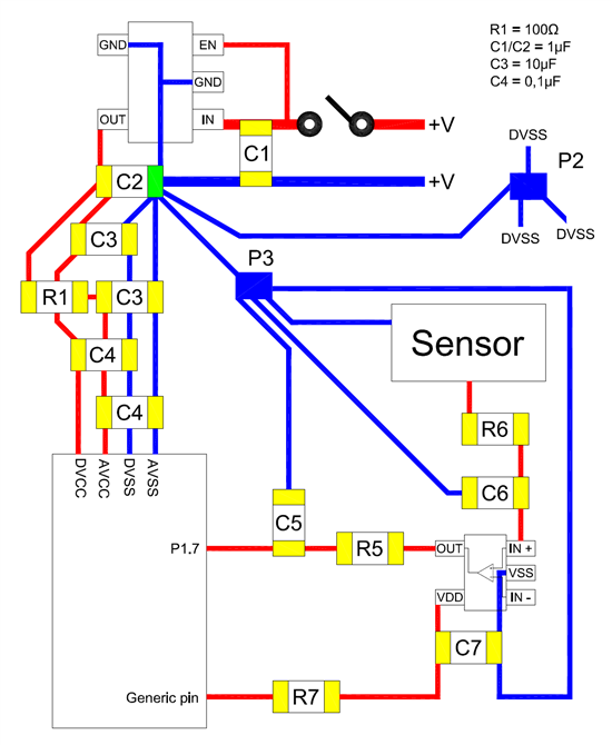
    This is very important (for me). In the picture below, I draw the microcontroller with all the capacitors I was talking about. You can see the capacitor at the output of LDO (C2) with the ground side in green colour; that’s the star-ground point.
    I even represented a second star-ground point (labelled “P2”), with many DVSS lines coming in. Another AVSS line goes directly to the main star-ground point. Is the scheme correct?
    Regarding the OpAmp; I have 3 analog grounds: 1 for the OpAmp, 1 for the filtering capacitor, and 1 for the signal source.
    Do I need 3 separated ground lines (connected at the main star-ground point), or can I use a second, analog star-ground point? Or maybe I can use 1 line for 2 grounds (i.e. the same ground line for the filtering capacitor + the signal source)?
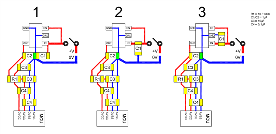
    Another question; I’ve always thought to use an LDO with 3 terminals (Vin, Vout, GND), but I’m thinking about using the TPS78225 (Vin, Vout, 2 GNDs and Enable pin, not used in my application).
    In the picture below, I draw 3 schemes, and the only difference is in the placement of the input capacitor (C1): are they equivalent?
    Marco

  • Marco2002 said:

    For me; This is a mesh!
    Marco2002 said:
    1 for the filtering capacitor

    There is no filtering capacitor in this design. If you want to filter something you need a special filter design (LC, RC etc) for it. Unless you mean the R1-C3 combo for AVcc.

    The 10uF and bigger capacitors are in general used as bulk-capacitor and can be placed anywhere, the currents here are relative slow and constant. Best place is there where you need them.

    Switching devices as a MCU can generate very low resistive shorts for a very short time, to avoid that these spikes will be transferred to the rest of your circuit you need to decouple the power to the device with just a little multilayer ceramic capacitor. But due to the high current you need to keep the inductance to the capacitor (as well the inductance of the capacitor himself) as low as possible, so place the capacitor very close to the MCU power connections. A value of 0.1 till 4.7uF is OK as long the mechanical size of the capacitor is small (= low ESR and low ESL). In case of a big MCU (large spikes) add ferrite beads to the Vcc.

    For a LDO regulator a 0.1-0.33uF capacitor at input side close to the LDO as in your drawing 3. On the output side at least a small capacitor (C2 and/or C3) also close to the LDO.

    Op-Amps are not really generating spikes but can draw a some (constant) current. When sharing the analogue sensor ground with the Op-Amp Return-GND can generate low voltage errors.

    To separate two grounds I create a component with two spots and a very small trace between them, so creating two net-names which simplifies, and avoids they are mixed during, routing the PCB.

    Some examples:

  • Hi Leo,
     
    As always, thank you for your answer. Reading it, I think that there was a misunderstanding.
    In my picture that you quoted, I showed ONLY the MCU, its decoupling capacitors (plus the resistor for AVCC), and ONLY the output capacitor of the LDO; it should be OK. Then, I added few picutres (1-2-3) to ask for an information: if I use an LDO like the TPS78225 (Vin, Vout, 2 GNDs and Enable pin, not used in my application), the proper way to place the ground side of the INPUT capacitor is:
    Picture 1) The star-ground point
    Picture 2) Beetween the star-ground and the negative pole of the battery
    Picture 3) On the other side of Picture 2)
    Which one is better?
    Then I wrote about the OpAmp, without drawing a picture; my fault.
    So, you can see below a picture with the complete scheme (but I don’t draw the resistors of the OpAmp beetween IN+, IN- and VSS).
    As always, the green pad is the main star ground point.
    P2 is a secondary star ground, for all the digital grounds.
    P3 is a secondary star ground, for all the analog grounds.
    R6 & C6: R/C filter for the signal from the sensor to the OpAmp.
    R5 & C5: R/C filter for the signal from the OpAmp to the MCU.
    R7 & C7: another possible solution to have a clean power supply at the OpAmp. I’ll try it, in comparison with the other ones that Jens-Michael Gross and Ilmars suggested me. The value of R7 will be very low.
    Leo Bosch said:
    A value of 0.1 till 4.7uF is OK as long the mechanical size of the capacitor is small (= low ESR and low ESL).
    For what I know, talking about SMD ceramic capacitors, the smaller the size, the higher the ESR; this is an important point (for me), because I'd like to switch from the case 0805 to the case 0603 for the bypass capacitors between the power lines, but I'm scared of the higher ESR of 0603.

  • It becomes more a mesh, and you are a slow reader too :)

    Marco2002 said:
    Picture 1) The star-ground point
    Picture 2) Beetween the star-ground and the negative pole of the battery
    Picture 3) On the other side of Picture 2)
    Which one is better?

    .

    As I wrote picture 3 is the best. Look from the source side, follow the current flow and treat a capacitor as a (AC) short. If you want to keep noise behind you, you must decouple backwards (to the source) and not pushing it forward to the star-point, so the LDO capacitors has nothing to do with your (forward) star-point and should be on-top of the LDO legs. A star-point is a point from where you want to keep the DC-levels as equal as possible and are not really noise suppressors or what else.

    Marco2002 said:
    P2 is a secondary star ground, for all the digital grounds.

    P2 is not important, it may also be a plane, there is no noise while you have proper decoupled your digital devices! (yes?)

    Marco2002 said:
    P3 is a secondary star ground, for all the analog grounds.

    And now we come to one of the mesh. P3 is directly connected to your C2-star-point. All currents, digital and analogue, goes true this point, the voltage level on this point will also alter and you can’t make an accurate measurement. P3 should be directly connected to the MCU-AVss to keep the analogue DC-level as equal as possible.

    Marco2002 said:
    R6 & C6: R/C filter for the signal from the sensor to the OpAmp.

    If it is necessary to filter your sensor, R6 & C6 should be on-top of your sensor (keep behind), if you want to filter the connection from your sensor to the Op-Amp then close to the Op-Amp.

    Marco2002 said:
    R5 & C5: R/C filter for the signal from the OpAmp to the MCU.

    Why amplifying noise first and then want to filter them out? Or do you expect TI makes noisy Op-Amps?

    Marco2002 said:
    R7 & C7: another possible solution to have a clean power supply at the OpAmp. I’ll try it, in comparison with the other ones that Jens-Michael Gross and Ilmars suggested me. The value of R7 will be very low.


    I don’t see any reason for R7, I would connect the Op-Amp Vdd directly to the AVcc, and maybe preferred from point R1-C3. If there is digital noise or voltage level change it will also be on this generic pin.

    Marco2002 said:
    For what I know, talking about SMD ceramic capacitors, the smaller the size, the higher the ESR; this is an important point (for me), because I'd like to switch from the case 0805 to the case 0603 for the bypass capacitors between the power lines, but I'm scared of the higher ESR of 0603.


    In general, on this application, any good ceramic capacitor will be suitable. But if you want to do your very best; Power Supply Decoupling needs low inductance (ESL), in stat using a 0603 use a (reverse) 0306. Low ESL is in most cases also low ESR, but some resistance will helps to avoid oscillation.

    For bulk/tank capacitors (power source) low ESR is more important. As I know ESR is defined by the dielectric material and not really by the mechanical size.

  • Hi Leo,
    As  Ilmars wrote on Dec 16 2013:
    “All your grounds (DVSS/AVSS) shall connect capacitor C1 at the output of LDO. (…) Don't forget that C1 GND is ground "bar" for every ground - for signal sources you measure either.”
    This is the reason for which I connected P3 that way. Maybe I’ve not correctly understood his words.
    C5 is the decoupling capacitor close to the ADC pin; I’ll remove R5.
    R7 & C7 could be useful just in case I won’t use the p-mosfet solution (connected to AVCC). The decoupling capacitor close to the OpAmp will block lower frequencies, higher ones could be blocked by R7 & C7.
    About ESR; you can take a look at  the following datasheet (pag. 13, figure 6 and 7).
    The dielectric material is the same, the capacitance is the same, as well as the rated voltage and temperature characteristic (X7R).
    But the 0603 case has an ESR which is 4 / 5 times higher than the 0805.
    The 0306 case isn’t good in this specific condition; between DVCC and DVSS there is AVCC, while between AVCC and AVSS there is DVCC. The 0306 case has not enough “free space” between its terminals. I could use the 0508, but, if possible, I’d prefer using the 0603 (if its ESR isn’t terrible; I’m not going to build a peace-maker, so I don’t need perfection).
    Marco

  • Marco2002 said:
    “All your grounds (DVSS/AVSS) shall connect capacitor C1 at the output of LDO. (…) Don't forget that C1 GND is ground "bar" for every ground - for signal sources you measure either.”

    Then maybe I don’t agree with it.

    Marco2002 said:
    C5 is the decoupling capacitor close to the ADC pin; I’ll remove R5

    What do you want to decouple here and I don’t think your Op-Amp will be happy to see C5.

    Marco2002 said:
    The dielectric material is the same, the capacitance is the same, as well as the rated voltage and temperature characteristic (X7R).
    But the 0603 case has an ESR which is 4 / 5 times higher than the 0805.

    I still doubt if this has to do with just the size; The graph can be wrong, there is a difference in construction between both etc, but anyhow the operating frequency is far too low, for decoupling you need to go over 100MHz.

    Marco2002 said:
    between DVCC and DVSS there is AVCC, while between AVCC and AVSS there is DVCC

    This is a failure of TI which they have corrected in newer devices.

  • Leo Bosch said:

    “All your grounds (DVSS/AVSS) shall connect capacitor C1 at the output of LDO. (…) Don't forget that C1 GND is ground "bar" for every ground - for signal sources you measure either.”

    Then maybe I don’t agree with it.

    [/quote]

    Then maybe look closer. Capacitor at LDO output is both- energy storage and HF noise filter and yet you connect both AVSS and DVSS through ground path coming from supply to ground lead of particular capacitor. Basically you can consider that LDO ground together with input/output capacitors are connected to DVSS and AVSS through ground wire which as we always assume has some resistance, so we can say: "connected through (pink) resistor":

  • In general this picture is Ok and would work. I was focused on the last picture and was too lazy to go back true hole the story and therefore carefully saying ‘maybe’.

    Nevertheless I would make some minor changes:

  • By the way (looking back) R1 should be calculated and as big as possible; R = ∆AV / Iav, for example 100mV / 1mA = 100Ω.

  • You better check DVSS ripple current path to LDO output C1 carefully and how it will affect AVSS ground noise :)

    [edit] assume that you have supply with worst possible ESR ever, like nearly depleted CR2032 battery

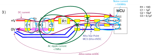
  • Or you better check my notes :); ‘ΔVss=some-mVDC’ which of course means that there will be some ΔAVss in respect to the LDO and his C1 but this has no influence on the analogue measurement. In your case you add also the MCU-ADC current to ΔVss which is unknown. Creating a (current less) analogue star-point on-top of the MCU-ADC results in a zero volt ΔAVss for all analogue signals (Sensor, Op-Amp & ADC) but not in respect to the power supply which is not important.

  • Leo Bosch said:
    ‘ΔVss=some-mVDC’ which of course means that there will be some ΔAVss in respect to the LDO and his C1 but this has no influence on the analogue measurement.

    Disagree. Because C1 of LDO output does not properly work as transient filter for DVCC ripple because C1 is connected in series with "pink resistor" - in result AVSS is getting DVSS ripple. How much - it depends on ESR of supply and resistance of (pink resistor) - ground bus between supply and LDO output capacitor.

**Attention** This is a public forum