This thread has been locked.

If you have a related question, please click the "Ask a related question" button in the top right corner. The newly created question will be automatically linked to this question.

calculating frequency of the pulse signal

Other Parts Discussed in Thread: CC430F5137

Hi,

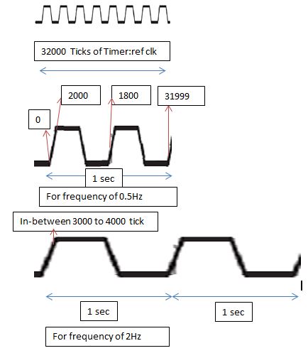
I am want to calculate the frequency of the incoming square pulse signal.For this I am planning to calculate the time period between two up transitions I mean the time interval between two consecutive 0 to 1 transitions.I will use CCS and CC430F5137 for this implementation.

can anyone suggest a method to find the time(interval) between two up transitions or any other method to find the time interval between two consecutive square pulses.So, the frequency will be the inverse of the this time interval.

Thanks.

  • Thanks and It looks like the one for which I am searching

    #include <msp430.h> 
    __interrupt TimerA0_ISR(void) // Note that the implementation of an ISR is compiler dependent
    {
      ++R10;
    }
    
    __interrupt TimerA1_ISR(void) // Note that the implementation of an ISR is compiler dependent
    {
      ++R11;
    }
    int main(void)
    {
        WDTCTL = WDTPW | WDTHOLD;	// Stop watchdog timer
    	// Timer TA1 is set by default
      P1SEL |= BIT6;
      TA1CCTL0 = CCIE; // interrupt enabled
    
      // Timer TA0 SMCLK/1
      TA0CTL = TASSEL_2; // clock source SMCLK
      TA0CCTL0 = CCIE; // interrupt enabled
      TA0CCR0 = 0x6000;
    
      //Measure
      R10 = 0;
      R11 = 0;
      TA0R = 0; // clear timer counter
      TA1R = 0; // clear timer counter
      TA0CTL |= MC0; // start timer
      TA1CTL |= MC1; // start timer
      while(R10 != 256); // Wait
      TA0CTL &= ~MC0; // stop timer
      TA1CTL &= ~MC1; // stop timer
      // R10 TA0 = 400 * 60000 = 24000000
      // R11 TA1 = Result
    	return 0;
    }

    I understood some lines like this from the datasheet

    1)  TA1CCTL0 = CCIE; // interrupt enabled

    In compare mode, any CCIFG flag is set if TAxR counts to the associated TAxCCRn value.Software may also set or clear any CCIFG flag. All CCIFG flags request an interrupt when their.Corresponding CCIE bit and the GIE bit are set. Page 409 slau259e.pdf

    Can I know in which mode it will run capture or compare?

    2)TA0R = 0; // clear timer counter

    The 16-bit timer/counter register, TAxR, increments or decrements (depending on mode of operation) with each rising edge of the clock signal. TAxR can be read or written with software. Additionally, the timer can generate an interrupt when it overflows.

    3)  TA1CTL |= MC1; // start timer

    // the timerA1 starts counting repeatedly counts from zero to the value of TAxCCR0(6000).

    4)For the first time when TAxCCR1 counts to 6000(to the value of TAxCCR0) then the TA1CTL sets to zero and after this how the programme works as I don't understand  the working of these lines

      TA0CTL |= MC0; // start timer

    while(R10 != 256); // Wait

    // why the value of 256

      TA0CTL &= ~MC0; // stop timer

      TA1CTL &= ~MC1; // stop timer

      // R10 TA0 = 400 * 60000 = 24000000

      // R11 TA1 = Result

    can anyone explain this.

    Thanks.

  • Timer TA0 is used for counting SMCLK (24 MHz) and TA1 for input signal, both with owerflow to registers. TA0 is aranged as 400 * 60000 = 24000000. When TA0 is finished (1 second), result is in stored in R11 TA1 without need for any number calculation/conversion.

    Value 256 is added by another user by mistake. It must be 400, not 256.

  • thanks and can I know

    What values will be present in the result in R11 TA1 if the incoming pulse signal is of 1 Hz and what values it will contain if the incoming pulse signal is of 2Hz. I mean how to calculate the frequency or time period of the incoming signal from the results value in R11 TA1.

  • Govardhan Reddy Patancheru said:
    I mean how to calculate the frequency or time period of the incoming signal from the results value in R11 TA1.

    If you use the external signal to clock the timer TA1, then the value will be the number of clock edges received in the 1-second time that TA0 was used to count. In other words, the value read will the the frequency directly in hertz.

  • I am planning to use TA0CTL = TASSEL_1 ;ACLK=32768hz for which I guess I have to use

    32768/6554=4.999=5

    TA0CCR0 = 0x6554;

    while(R10 != 5);

    1)Is this the right of calculating ? Can someone explain if anything is wrong and anything extra are to be changed for the required.

    2)what are things to be taken into consideration if the frequency meter has to detect only the frequency range of 0.5 to 2.5Hz.

    Thanks.

  • Govardhan Reddy Patancheru said:
    2)what are things to be taken into consideration if the frequency meter has to detect only the frequency range of 0.5 to 2.5Hz.

    Then you have to use clock you measure as gate signal and count reference clock periods during incoming clock period. If reference clock is just (slow) 32kHz perhaps you need more than single period if incoming freq > 1Hz so your gate time is always not less than 1sec. For reasonable results I would use 20MHz TCXO oscillator as reference instead

    [edit] Using 32768 Hz to measure 1Hz you have +/- 1 pulse uncertainty (as always). So 1Hz can show as 0,99997 Hz or 1,00003 Hz. If this is ok then do it

  • Can I know in which mode it will run capture or compare?

    It is defined by the CAP bit in the CTL register. The default is compare mode.

    3) TA1CTL |= MC1; // start timer
    // the timerA1 starts counting repeatedly counts from zero to the value of TAxCCR0(6000).

    No. MC1 sets the upper bit of the MC field in the control register. This puts the timer into continuous mode where it counts from 0 to 65535. MC_1 (note the underscore) puts it into up mode. Also, this is TA1CTL, so it would (if at all) require the use of TA1CCR0. But it is TA0CCR0 that is set to 0x6000. (and 0x6000 isn't 6000 but 6*2^12 = 24576.

    TA0CTL |= MC0; // start timer

    This sets BIT0 of the MC filed. If the MC field was clear before (default), it puts the timer from stop mode into up mode. MC0 has the same value as MC_1. And MC_3 (UP/down mode) is the same as (MC1|MC1)

    while(R10 != 256); // Wait
    // why the value of 256

    Why not? It waits for the timer CCR0 ISR being called 256 times. (se below)

    TA0CTL &= ~MC0; // stop timer

    It clears the MC0 bit which was set before for UP mode. Same for

    TA1CTL &= ~MC1; // stop timer

    clearing MC1 bit, switching the timer form cont mode to stop mode.

    // R10 TA0 = 400 * 60000 = 24000000

    This line is apparently a relic form different code settings, where R10 was checked for 400 and not 256, and TA0CCR0 was set to 60000 and not 0x6000.
    It gives the number of TimerA0 ticks for which TimerA1 was counting incoming clock pulses. On SMCLK of 24MHz, this originally was one second, so the count of TimerA1 is the average pulse frequency. Looks liek the code was originally written for a 5x family MSP running on 24MHz.

    But with 0x6000 and 256 and a default SMCLK frequency of, well, what MSP do you use? 2x family? Then ~1.05MHz this gives ~1/6 second interval and TA1R needs to be multiplied by 6 for the frequency.

  • Thanks for the above explanations.

    I am using CC430F5137.So, from the IImars suggestion I am planning to use SMLCK=1.05Mhz.

    Then if I use TA0CCR0=60000 => 1.05Mhz / 60000=17.5Hz and using the condition of while(R10 != 17); will give  ~1020000Hz= ~1.2Mhz.

    But 1.2Mhz will not make the 1 second exactly. Can someone guide with the better calculation for this.

  • Govardhan Reddy Patancheru said:

    Thanks for the above explanations.

    I am using CC430F5137.So, from the IImars suggestion I am planning to use SMLCK=1.05Mhz.

    Then if I use TA0CCR0=60000 => 1.05Mhz / 60000=17.5Hz and using the condition of while(R10 != 17); will give  ~1020000Hz= ~1.2Mhz.

    But 1.2Mhz will not make the 1 second exactly. Can someone guide with the better calculation for this.

    You seem like you understand the concept better. There is nothing magical or set-in-stone about the numbers (eg. 60000). Surely you can adjust them yourself and come up with a set that match you needs perfectly. You might even use a spreadsheet for that.

    I think we'd be more willing to verify a set of numbers for you then to do all the work for you.

  • I think we'd be more willing to verify a set of numbers for you then to do all the work for you.

    I think using TA0CCR0=58254 will be the better solution 1048576/58254=18 (R10! =18).

    And I also think there is a need for the ADC channel settings to read the incoming signal. If so, can someone explain the instructions to add ADC channel configuration to read the incoming signal with this frequency counter.

    Thanks.

  • Govardhan Reddy Patancheru said:
    But 1.2Mhz will not make the 1 second exactly. Can someone guide with the better calculation for this.

    I don't think you understand how to measure <= 2.5Hz frequencies or I just did not tell it well. Please read my post very carefully again, pay special attention to this part: you have to use clock you measure as gate signal and count reference clock periods during incoming clock period.

  • Yes, I am not that clear with this

    Reference clock (gate signal) =32Khz =>0.03 ms  and  Incoming signal=1.5Hz=>0.7 sec

    1) If reference clock is just (slow) 32 kHz perhaps you need more than single period if incoming freq > 1Hz so your gate time is always not less than 1sec.

    2) previously I thought to use 32Khz as my ADC CLK source and later understood from my other post here  http://e2e.ti.com/support/microcontrollers/msp430/f/166/t/322317.aspx that I need  ADC CLK source>4.5MHz so using 1Mhz(SMCLK) for both purposes.

    SMCLK selected and TA0CCR0=58254 then I need  to run the TA0CCR0 18 times to finish 1second duration of the reference clock 1048576/58254=18 (R10! =18).

    After (R10! =18) then we need to check the counts in the Timer A1 which was counting incoming clock pulses. But I also didn’t understood of what will be the value in R11(as the timer Timer A1 will be running in the continuos mode which counts upto 0FFFFh(65535) and starts again from zero)if reference clock has finished 1 second count duration if incoming signal pulse signal is of 1Hz or 1.5Hz.

    3)Is there a need for the ADC channel settings to read the incoming signal. 

    Could you please explain about these.

  • Forget about that code using two timers. It is not useable for low freq measurements (0.5 - 2.5Hz) unless you are ok with 100% or even greater error.

    When you measure slow clock that's way slower than reference - you shall measure period, not frequency! When  you know period it's easy to calculate frequency

    Run timer at 32KHz, connect input freq to capture pin, capture on rising edge only. Capture two (consecutive) rising edges of input signal, substract those two captures to get reference ticks between two rising edges of input signal. Then it's easy to calculate freq: timer_freq/(Capture_current-Capture_prev). Perhaps you will want to increase precision by measuring more than single input clock period, this would be good idea if freq > 2Hz.

    Note that it's just generic explanation that does not account for timer rollovers.

  • Thanks Ilmars for the implementation method you explained for my requirement of 0.5 to 2.5 Hz count.

    1)ButI didn't understood  this line  of Jens explained "This line is apparently a relic form different code settings, where R10 was checked for 400 and not 256, and TA0CCR0 was set to 60000 and not 0x6000.
    It gives the number of TimerA0 ticks for which TimerA1 was counting incoming clock pulses. On SMCLK of 24MHz, this originally was one second,On SMCLK of 24MHz, this originally was one second" here 

    http://e2e.ti.com/support/microcontrollers/msp430/f/166/t/322643.aspx

    Because each timer was set to count 60000 ticks *400 ticks ;total=24000000 ticks=24MHz of SMCLK which should be equal to 1/24Mhz =4.1 *10^-8 seconds.But how this 24Mhz will be 1 sec.

    2)can I get any examples or links for above mentioned implementation method to use timer for capturing two rising edges input pulse signal.

    Thanks.

  • Govardhan Reddy Patancheru said:

    Because each timer was set to count 60000 ticks *400 ticks ;total=24000000 ticks=24MHz of SMCLK which should be equal to 1/24Mhz =4.1 *10^-8 seconds.But how this 24Mhz will be 1 sec.

    In my freq meter (first reply in topic) is used 24 MHz MCLK (XT2) on MSP430F550x, and for 1 seconds it will take 24000000 (400 * 60000) ticks. It will work also with any other MCLK with changing 400 * 60000 part, so for example with 1 MHz MCLK, 1 second period will be 1000000 (20 * 50000).

  • Hi,

    I am getting confused with this, so can I get some clarification from anyone of you about this

    --If the zrno soli 's frequency meter implementation(as posted in the part of this thread) with two timer is used with my requirement of counting freq in the range of 0.5 to 2.5Hz.

    How this is not  "useable for low freq measurements (0.5 - 2.5Hz) unless it is ok with 100% or even greater error." as Ilmars said.

    Thankyou.

  • Govardhan Reddy Patancheru said:
    I am getting confused with this

    Please tell which of two hints you do not understand:

    1) "When you measure slow clock that's which is way slower than reference - you shall measure period, not frequency!

    2) "count reference timer ticks between two rising edges of input signal".

    You shall look not for frequency measurement code but for using timer capture to measure pulse length.

    Use this forum search, keywords measuring pulse

  • I understood in the following way and please correct if I am wrong with anything

    If the 32Khz clck is used as timer clk source then it needs 32000 timer ticks compared to the 1000000 ticks needed for the 1Mhz.so, 32Khz clk source is fast for this purpose compared to the 1Mhz.

    If the incoming pulse signal is measured for 1 seconds interval of 32khz then only two rising edges will be detected for 2Hz(0.5sec) input signal  and only 1 rising edge will detected for 0.5Hz(2 sec)  in this duration.


    From my understanding I was able to make this for counting reference timer ticks between two rising edges of input signal

    P3SEL |= BIT1;

    TA0CTL = TASSEL_1; // clock source ACLK

    TA0CCTL0 = CCIE; // interrupt enabled

    TA0CCTL0=MC1;//continuous mode

    TA0CCTL0=CAP1;//for capture mode

    TA0CCTL0=CM2;// Capture on rising edge

    And can you please explain me what else are needed for this.

    Thanks.

  • Govardhan Reddy Patancheru said:
    If the 32Khz clck is used as timer clk source then it needs 32000 timer ticks compared to the 1000000 ticks needed for the 1Mhz.so, 32Khz clk source is fast for this purpose compared to the 1Mhz.

    What?? - NO! Sorry, I think I already explained everything you need to know. If you have any problems with that - read again and again

    Govardhan Reddy Patancheru said:
    And can you please explain me what else are needed for this.

    You don't even bother to read whole posts carefully :( In my previous post I already told you:

    Capture two (consecutive) rising edges of input signal, substract those two captures to get reference ticks between two rising edges of input signal. Then it's easy to calculate freq: timer_freq/(Capture_current-Capture_prev).

    Also I told you to use search in this forum.

    Perhaps reading following articles can help to get better understanding of the subject:

    http://www.leapsecond.com/pdf/an200.pdf

    http://www.leapsecond.com/pdf/an200-3.pdf

  • I went back and read your posts. Sorry, I didn’t really get these

    1) you said here “When you measure slow clock that's way slower than reference - you shall measure period, not frequency”

    If possible can you please try to explain me about this.

    2) For this “Run timer at 32KHz, --first clock represents the timer clock of 32000 ticks for 1 sec(in my last reply diagram) connect input freq to capture pin, capture on rising edge only. Capture two (consecutive) rising edges of input signal—as shown with 0.5Hz and 2Hz pulse signal of rising edges(in my last reply diagram), substract those two captures to get reference ticks between two rising edges of input signal”--reference ticks obtained=18000-2000=16000 (as shown in the my last reply diagram)

    Your above saying was diagrammatically illustrated as shown in my last post. Can you please explain what is wrong with my diagrammatical representation or assumption.

  • Govardhan Reddy Patancheru said:
    Can you please explain what is wrong with my diagrammatical representation or assumption.

    You show 0.5Hz signal having two periods per second. This is 2Hz, not 0.5Hz. Also 32kHz XTAL gives 32768 Hz, not 32000 Hz. Half of 31999 is not 1800 but 15999.

    Govardhan Reddy Patancheru said:
    32Khz clk source is fast for this purpose compared to the 1Mhz.

    Wrong. 1MHz is faster than 32KHz, thus you get better resolution using 1MHz compared to 32KHz.

    Govardhan Reddy Patancheru said:
    If the incoming pulse signal is measured for 1 seconds interval of 32khz then only two rising edges will be detected for 2Hz(0.5sec) input signal  and only 1 rising edge will detected for 0.5Hz(2 sec)  in this duration.

    You don't measure pulse signal "for 1 second", at least in proposed by me method. What if pulse period is longer than 1 second as in your case of 0.5Hz? THen you don't get 2nd rising edge at all. So you just don't set exact time windows which will be used to capture two edges of incoming signal. So please do your homework- read timer chapter of User's Manual, get better understanding how to measure time intervals using timer and it's CCR registers.

  • Apologies for mistake of mine that probably led you off-track. Correct calculation of freq=Freq_reference/(capture-capture_previous). I will correct original post too

  • 1 second is 1 second. It does not mater if you use a grandfather clock (to count to 1) or a 16MHz clock (to count to 1000000). They cannot speed up or slow down 1 second.

  • old_cow_yellow said:
    1 second is 1 second. It does not mater if you use a grandfather clock (to count to 1) or a 16MHz clock (to count to 1000000). They cannot speed up or slow down 1 second.

    We are trying to solve puzzle measuring 2 second period in 1 second time window. Still have no idea

  • Sorry,

    for this 1)"You show 0.5Hz signal having two periods per second. This is 2Hz, not 0.5Hz." 

    While making the diagram I wrongly added 0.5 Hz instead of 2Hz and 2Hz instead of 0.5Hz 

    which was written correctly in my last post like"If the incoming pulse signal is measured for 1 seconds interval of 32khz then only two rising edges will be detected for 2Hz(0.5sec) input signal  and only 1 rising edge will detected for 0.5Hz(2 sec)  in this duration."

    2) "Also 32kHz XTAL gives 32768 Hz, not 32000 Hz. Half of 31999 is not 1800 but 15999".I just assumed it as the clk as 32KHz for easy analysis or calculation.

    3)"You don't measure pulse signal "for 1 second", at least in proposed by me method. What if pulse period is longer than 1 second as in your case of 0.5Hz? "

    Yes,I remember that you ( )informed me about this so many times this before, but I was referring to 1 sec interval for my understanding.


  • Timing devices usually use two different methods for measuring an input frequency (as already suggested earlier in the thread): If the input signal is fast compared to the reference clock, a fixed number of reference clock ticks is used to measure the number of input clock ticks during this time.

    Assuming 32768Hz reference clock, frequencies above, say, 100Hz, a measured by counting the number of input pulses during a 1s period. Frequencies below 100Hz are measured by counting the number of reference pulses during one single input period. This way you have a fair resolution for high and low frequencies.

    Depending on the result of the last period, you can switch between the two methods. You can also use an additional divider, to reduce the reference counts for lower frequencies (or 0.5001Hz would be the limit in this example)

  • Thanks for the explanation so far and I started to like this

    1) Set the timer to 32Khz TA0CTL = TASSEL_1;ACLK

    2)  TA0CCTL0 = CCIE; // interrupt enabled

    TA0CCR0=32768

    3)set timer in up mode TA0CTL |= MC_1

    4)TA0CTL |= MC0; // start timer

    5) TA0CCTL1|=CAP_1;//for capture mode

    6) TA0CCTL1|=CM_1;//capture on rising edge

    7)Using 32768Khz will have 32768 timer ticks

    For first second: If we use Timer in Upmode and use CCR0=32768 then couting from 0 and it reaches 32767 (32768 ticks=32768 Khz=1 second) ticks there will be timer interrupt where the a variable let say x will be incremented.

    For next second: When the timer starts counting from 0 and reaches 32767 ticks the variable will be incremented again (x=2)

    __interrupt TimerA0_ISR(void)

    {

    TACLR=0;

      x=x+1;

    If(x==2)

    {

    X=0;

    }

    }

     So, the rising edges of pulse signal will be measured for every 2 seconds interval of 32Khz such that it can used to measure the 0.5 Hz frequency as well.

    But how to get the difference of ticks between the two captured rising edges.I  mean how to make the condition using the below with the above to get the difference of ticks between two consecutive the captured rising edges.

    In the user manual it says “A capture occurs on the selected edge of the input signal. If a

    capture occurs:

    • The timer value is copied into the TAxCCRn register.

    • The interrupt flag CCIFG is set.”

    Can someone correct me if anything is wrong with the above and also need suggestions to get the difference of ticks between two captured rising edges.

  • Govardhan Reddy Patancheru said:
    But how to get the difference of ticks between the two captured rising edges.

    By substracting captured timer register values.

    Substract previous value (which supposedly is smaller) from current capture.

  • Ilmars said:
    Substract previous value (which supposedly is smaller) from current capture.

    And if previous value is larger, then you know that the counter wrapped around. So in that case (you have to test for to decide which calculation to do) you need to add the max timer value to the current capture before the subtraction.

    pseudocode:

    if(current < previous) current += 65536; // for 16-bit counter, make sure variables are bigger than 16 bits though

    ticks = current - previous;

  • If using unsigned int, just take the difference (the subtraction result). If there was a wrap-around, it still gives the right result (as if the signed difference value did have 0x10000 added if negative)

    The only problem Is that you don't know how many wrap-arounds happened. If first capture is 0xF000 and second is 0x1000, difference is 0x2000. But could also be 0x12000 or 0x22000. Due to the 16 bit counter size, this ambiguity cannot be resolved except if timer overruns are counted (and the code is getting a bit complex then, to avoid racing conditions)

  • Thanks and I got these doubts

    1)If we assume that we are measuring 2Hz pulse signal then we have 2 rising edges in the 1 second interval of 32,768Khz where the timer counts from 0 to 32767(CCRO value) ticks.

    But what is method to be used to check the timer value in the TAxCCRn register.I mean should we check the timer register after each tick of the timer because

    when a capture occurs on the selected edge of the input signal

    • The timer value is copied into the TAxCCRn register.

    • The interrupt flag CCIFG is set.”

    I am planning to use this for subtraction purpose: when it is started it should save the first obtained timer value of respective rising edge into some variable say current and when next  timer value is captured the current value should be saved into previous here the substraction will be done between current and previosu as explained in the above posts of .Again when next timer value is captured the current value should be saved into previous.

    Is there any other simple solution for this

    2)As I am only using timer (CCR0=32767) should I add 32767 instaed of 65536 here 

    if(current < previous) current += 32767(65536); 

    can you help me out in solving the above.

  • Govardhan Reddy Patancheru said:
    2)As I am only using timer (CCR0=32767) should I add 32767 instaed of 65536 here 

    There's no rational reason to push timer roll-over each 1 second instead of 2 seconds.

    Govardhan Reddy Patancheru said:
    save the first obtained timer value of respective rising edge into some variable say current and when next  timer value is captured the

    You don't save timer value! Perhaps you need to read User's Guide to get better understanding about timer capture. 

    volatile unsigned int ccr_previous;
    
    CCR1_ISR()
    {
    unsigned int ccr_current;
    
      ccr_current = TAxCCR1;
    
      if(ccr_current < ccr_previous) {
        freq = 32768 / (ccr_current + 65536 - ccr_previous);
      } else {
        freq = 32768 / (ccr_current - ccr_previous);
      }
    
      ccr_previous = ccr_current;
    }
    

  • Thanks IImars,

    Now I made this 

    __interrupt TimerA0_ISR (void) 
    {
    TACLR=0;
    }
    CCR1_ISR() 
    { 
    unsigned int ccr_current; 
      ccr_current = TA0CCR1; 
      if(ccr_current < ccr_previous) { 
        freq = 32768 / (ccr_current + 65536 - ccr_previous); 
      } else { 
        freq = 32768 / (ccr_current - ccr_previous); 
      } 
      ccr_previous = ccr_current; 
    y=y+1;
    freq(y)=freq;
    }
    int main(void)
    {
     WDTCTL = WDTPW | WDTHOLD; 
    //TA0CCR0: Reference clock
    TA0CTL = TASSEL_1;ACLK
     TA0CCTL0 = CCIE; // interrupt enabled
    TA0CCR0=32768;
    TA0CTL |= MC_1;// set timer in up mode
    TA0CTL |= MC0; // start timer
    //TA0CCR1: It will read the input pulse signal
     P3SEL |= BIT2; //it is connected to TA0CCR1A
    TA0CCTL1|=CAP_1; //for capture mode
    TA0CCTL1|=CM_1; //capture on rising edge
     while(1)
     {
      if(y==2) //calculate freq if two rising edges were captured 
         {
              freq_nedeed=freq(1)+freq(2);
              //transmit freq_needed through UART to the terminal
              y=0;
          }
      }
    }

    can I know how to write the correct Interrupt service routine in place of this CCR1_ISR() 

    Also Can someone correct if I am wrong with the above and if anyhting else is needed for this.

  • Govardhan Reddy Patancheru said:
    can I know how to write the correct Interrupt service routine in place of this CCR1_ISR() 

    By looking into source code examples?

    Wait... what's this:

    freq(y)=freq;

  • sorry,for the wrong assigment freq(y) is basically an array it should be different from freq so, I will use this instead freq1(y)=freq;

    Can you suggest me if anything else is needed or wrong for the measuring incoming pusle signals frequency in the range of 0.5 to 2.5Hz as I am new to timers.

    Thankyou.

  • Govardhan Reddy Patancheru said:
    Can you suggest me if anything else is needed or wrong for the measuring incoming pusle signals frequency in the range of 0.5 to 2.5Hz as I am new to timers.

    Your code have just main bits and pieces of freq measurement. There's lot of things to change or add like synchronization of main loop to freq measurements, checking array bounds and so on. Honestly it seems to me that you are new not only to timers but C programming as such (no offense).

    Correct answer:

    freq1[y]=freq;

  • If possible can you please give some hints regarding this :Synchronization of main loop to freq measurements

    Thanks.

  • Govardhan Reddy Patancheru said:
    Synchronization of main loop to freq measurements

    If you don't stop main loop then it executes very fast doing nothing, consuming 99.99% power or even more just to generate heat. Better stop CPU and wait for timer capture ISR. There's many source code examples showing how to do it.

  • Thanks for the guidance and the suggestions.Now,I made the required things like this

    //CCR1 Interrupt service routine:
    #pragma vector=TIMERA0_VECTOR
    __interrupt void Port_3(void)// P3SEL |= BIT2;
    {    
    //frq calculation
     __bic_SR_register_on_exit(CPUOFF);//wakes up CPU from OFF
    }
    //Timer Interrupt
    #pragma vector=TIMERA0_VECTOR
    __interrupt TimerA0_ISR (void)
    {
    TACLR=0;
     __bic_SR_register_on_exit(CPUOFF);//wakes up CPU from OFF
    }
    
    //CPU OFF+waits for timer interrupts
    int main(void)
    {
    while(1)
    {
     if(y==2) //calculate freq if two rising edges were   
       { 
        freq_nedeed=freq[1]+freq[2];
        //transmit freq_needed through UART 
        y=0; 
       }
    __bis_SR_register(CPUOFF + GIE);//makes CPU OFF and enables interrupts
    }
    }


    Still need your suggestions to make it ,if anything is missing.

  • Govardhan Reddy Patancheru said:
    Still need your suggestions to make it ,if anything is missing.

    Do you really think such approach is effective way of learning embedded C programming?

    Compile code and try to debug it. I am not your debugger ;)

    [edit] It's impossible to learn swimming in the empty pool

  • It is not showing errors or warning when built ,but it shows the following error when debuged it .

    I am suing CC430f5137 with CCS5


    there are related linke here

    http://e2e.ti.com/support/development_tools/code_composer_studio/f/81/t/212308.aspx

    http://e2e.ti.com/support/development_tools/code_composer_studio/f/81/t/162331.aspx

    I tried them by creating new project but the same error is coming out 


    #include <msp430.h> volatile int ccr_current=0,ccr_previous=0,y=0,freq1[3],freq=0,freq_needed=0; //Timer Interrupt #pragma vector=TIMER0_A0_VECTOR __interrupt void TIMER0_A0_ISR(void) { __bic_SR_register_on_exit(CPUOFF);//wakes up CPU from OFF } #pragma vector=TIMER0_A0_VECTOR __interrupt void Port_3(void)// P3SEL |= BIT2; { unsigned int ccr_current; ccr_current = TA0CCR1; if(ccr_current < ccr_previous) { freq = 32768 / (ccr_current + 65536 - ccr_previous); } else { freq = 32768 / (ccr_current - ccr_previous); } ccr_previous = ccr_current; y=y+1; freq1[y]=freq; __bic_SR_register_on_exit(CPUOFF);//wakes up CPU from OFF } int main(void) { WDTCTL = WDTPW | WDTHOLD; //TA0CCR0: Reference clock TA0CTL = TASSEL_1; TA0CCTL0 = CCIE; // interrupt enabled TA0CCR0=32768; TA0CTL |= MC_1;// set timer in up mode TA0CTL |= MC0; // start timer //TA0CCR1: It will read the input pulse signal P3SEL |= BIT2; //it is connected to TA0CCR1A TA0CCTL1|=CAP; //for capture mode TA0CCTL1|=CM_1; //capture on rising edge while(1) { if(y==2) //calculate freq if two rising edges were captured { freq_needed=freq1[1]+freq1[2]; //transmit freq_needed through UART to the terminal y=0; } __bis_SR_register(CPUOFF + GIE);//makes CPU OFF and enables interrupts } }

    can someone help me in solving this .

  • When you get load file error first thing you do - check that file exists.

    In case there's no file then you find reason why it is so

**Attention** This is a public forum