This thread has been locked.

If you have a related question, please click the "Ask a related question" button in the top right corner. The newly created question will be automatically linked to this question.

Why am I getting unwanted pulse in generating complementary pwm signal using msp430 up/down mode?

Other Parts Discussed in Thread: MSP430G2553

Hi,

I am trying to generate 2 complementary sinusoidal PWM signals using msp430g2553. I want to use those as unipolar SPWM to drive a full-bridge.

Spec:

Reference Signal = 50 Hz

Triangular Signal = 2.5 kHz

pwm period = 0.4ms or 400 us

dead time between 2 signals = 1 us (this is why I am using up/down mode and Timer1_A3)

However, I am getting below output in the oscilloscope:

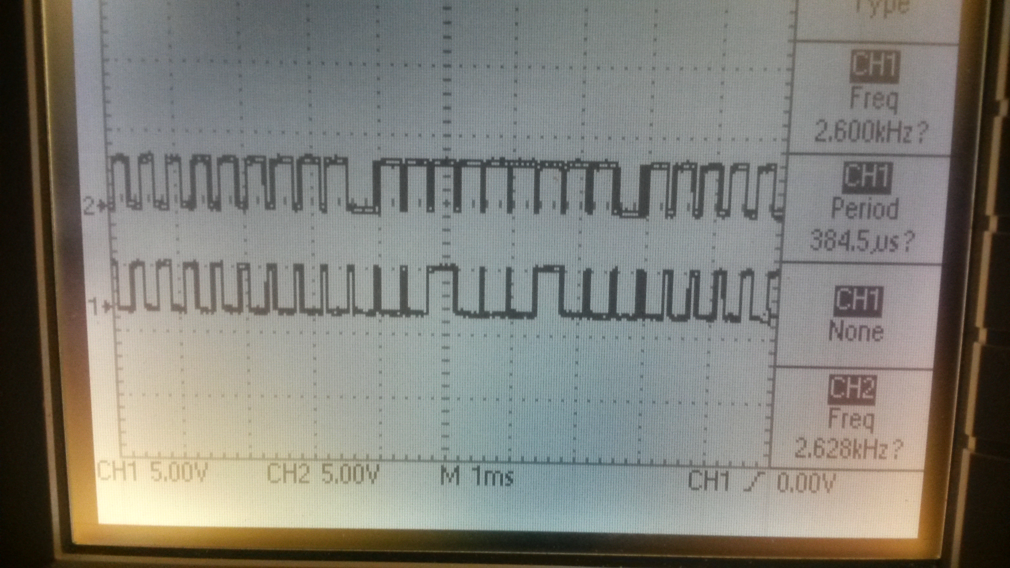
I am not sure why few pulses are out of shape. What am I doing wrong? Below is my code for your review. Any help is highly appreciated.

#include  <msp430g2553.h>

const unsigned int phalfcycle[25] = {100, 110, 120, 129, 139, 147, 155, 162, 168, 172, 176, 179, 180, 180, 179, 176, 172, 168, 162, 155, 147, 139, 129, 120, 110};
const unsigned int complementary[25] = {99, 109, 119, 128, 138, 146, 154, 161, 167, 171, 175, 178, 179, 179, 178, 175, 171, 167, 161, 154, 146, 138, 128, 119, 109};

unsigned int index = 0;

void main(void)
{
  WDTCTL = WDTPW + WDTHOLD;                 // Stop WDT

  //Calibrate DCO for 1MHz operation
  BCSCTL1 = CALBC1_1MHZ;
  DCOCTL = CALDCO_1MHZ;

  P2DIR |= BIT1 + BIT4;                            // P2.1 and P2.4 pwm output

  TA1CCR0 = 200 - 1;                               // PWM Period/2; period is 0.4ms or 400us

  TA1CCTL0 = CCIE;									// CCR0 interrupt
  TA1CCTL1 = OUTMOD_6;                         // CCR1 toggle/set
  TA1CCTL2 = OUTMOD_2;							// CCR2 toggle/reset as complementary
  TA1CTL = TASSEL_2 + MC_3 + TACLR;                  // SMCLK, up-down mode

  _BIS_SR(LPM0_bits + GIE);                       // Enter LPM0
}


#pragma vector=TIMER1_A0_VECTOR						// ISR for CCR0
__interrupt void Timer_A0 (void)
{
	TA1CCR1 = phalfcycle[index] - 1;
	TA1CCR2 = complementary[index] - 1; 			// deadtime = 1us

			index = index + 1;
			if(index == 25)
			{
				index = 0;
				P2SEL ^= BIT1;
				P2SEL ^= BIT4;
			}

}

  •  Hi, many issue are present and not simple to isolate.

     First if you have fixed dead time is better calculate than have two vector, this save computing time is one of problem generating your errant issue.

     Seond too many operation are between setting of Timer register, so less operation less probable hit change between pulses.

     Raising clock can help but root solution is forever better than work around.

     Interrupt used for update is the wrong one, it is better use TAIFG fired when counter reach zero,

    so next PWM pulse is symmetrical than asymmetric on top of UP/DOWN can generate issue when too close to next cycle.

     Hint:

    declare deadtime as constant than hardwire.

    use TAIFG

    remove useless calculation and shorten PWM update.

    Tahsina Hossain Loba9 said:
    TA1CCTL0 = CCIE; // CCR0 interrupt

     Disable

    Tahsina Hossain Loba9 said:
    TA1CTL = TASSEL_2 + MC_3 + TACLR; // SMCLK, up-down mode

    Enable TAIFG interrupt

    Tahsina Hossain Loba9 said:
    pragma vector=TIMER1_A0_VECTOR // ISR for CCR0 __interrupt void Timer_A0 (void) {

    move to IRQ_1

    Tahsina Hossain Loba9 said:
    TA1CCR1 = phalfcycle[index] - 1; TA1CCR2 = complementary[index] - 1; // deadtime = 1us

    shorten code execution time:

    static int nextPWM1=0,nextPWM2=0;

    TA1CCR=nextPWM1;

    TA2CCR=nextPWM2;

    nextPWM1=halfcycle[index++];

    if(index>NUMSamples) index=0; // roll index

    if(nextPWM1>DeadTime)

    nextPWM2=nextPWM1-DeadTime;

    else

    nextPWM1=nextPWM2=0; // less than dead time stop PWM

     if one has to be subtracted then subtract from sample array not on interrupt!!

  • Hi Roberto,

    Thanks a lot for your reply. I could not interpret few things you said. When you said, enable TAIFG interrupt, I can do that by following statement right?

    TA1CTL = TASSEL_2 + MC_3 + TACLR + TAIE;

    So now, there will be case 10 (TAIFG) interrupt in TA1IV vector. But what action should I take when TAIFG occurs? Again, if I disable TA1CCTL0 interrupt then where to update the TA1CCR1 and TA1CCR2? Could you please point these in my previous code?

    Thanks again.
    Tahsina
  • Timer_A does not have a Latch like Timer_B

    So when you get weird pulse pauses, most of the time is it that with Timer A:
    The event have already occurred or will occur again if you change ccr1 or ccr2 to a higher value.
     
    The lowest number you have is 100, so if you fine tune the ISR to be faster you should not miss it.
    But the lowest numbers is at the same time as end of array and extra code is handled at this only moment.
    Roll the array data by 50% so worse case scenario don't happen at the same time.

    Should use TAIFG, though normally you waste a few cycles trying to figure out who issued the IRQ,
    but as CCR1 and CCR2 have their IRQ disabled, No TA0IV re-jumps needed. Read it anyway as to clear the IFG flag

  • Tony Philipsson said:
    Timer_A does not have a Latch like Timer_B

     Right G2553 has two timer A with 3 CCR register so need to avoid races.

     I like your graph explaining where interrupt are fired, maybe this artistic can help understand more than reading Data sheet ;) if it is not so difficult, please also add IRQ from one channel so we can use for future reference.

  • Tahsina Hossain Loba9 said:
    Thanks a lot for your reply. I could not interpret few things you said. When you said, enable TAIFG interrupt, I can do that by following statement right?

    TA1CTL = TASSEL_2 + MC_3 + TACLR + TAIE;

     This is right, and this is the best interrupt for your condition as is far from edges and never change close to one side of PWM pulse.

    Tahsina Hossain Loba9 said:
    So now, there will be case 10 (TAIFG) interrupt in TA1IV vector.

     Ok

    Tahsina Hossain Loba9 said:
    But what action should I take when TAIFG occurs?

     All it was in TA0 affected by pulse errant behaviour, here is far from toggling so don't change after event is fired. As Tony said Timer A is not latch buffered as is Timer B and no timer B is on 2553.

    Tahsina Hossain Loba9 said:
    Again, if I disable TA1CCTL0 interrupt then where to update the TA1CCR1 and TA1CCR2

     All was in your previous code modified as I suggested, no complete code, please do your work and then if doesn't work we can give another hint.

     Code I rewrote was an hint on how your code has to be rewritten, declare both static variable at begin of IRQ handler then copy code I wrote on correct position, if more is necessary also add that.

     So set both CCR register from local static variables then retrieve next value and calculate dead time and all math is necessary as short as possible.

     Another thing I remember you set two bit of same register using two instruction, use one instead to save time and power too.

     P2SEL &= ~BIT1;

    P2SEL &=~BIT4;

     use instead single instruction

    P2SEL &= ~(BIT1 | BIT4);

     your case

    P2SEL ^=  BIT1 | BIT4;

     what is your goal toggling these bit?

     Sorry assistance is ok, rewrote wrong code for free it isn't.

  • Thanks a lot for all the help.
  • Thanks a lot. I will try the things you suggested.
  • Tahsina Hossain Loba9 said:
    Thanks a lot for all the help

     When you have finished post again all code as attachment so we check your progress and if necessary give more hint.

     Please understand we need raise level of forum and not serve all come here for free. Who wish grow up is welcome the other just screaming for ready solution not.

**Attention** This is a public forum