
- Ask a related questionWhat is a related question?A related question is a question created from another question. When the related question is created, it will be automatically linked to the original question.
Good morning!
I have prepared this code inspired on an example from TI. I want to communicate my MSP432 through SPI to an external device. I use USCB0 since it is useful for my own launchpads! :) The external device works because I did this same code for MSP430G and it works perfectly.
Ok, let's go through it. Do not laugh very loud since it is my first MSP432 & DriverLib attempt. Hope it will avoid some register tweaking in my future life if I ever get comfortable enough with it. Great lib, by the way.
Here comes the code!
/*
 * ACLK = ~32.768kHz, MCLK = SMCLK = DCO ~ 1MHz
 *
 * MSP432 = SPI master, external device = SPI slave
 *
 *                MSP432P401
 *              -----------------
 *             |                 |
 *             |            P4.3 |-> CS
 *             |                 |
 *             |            P1.6 |-> Data Out (UCB0SIMO)
 *             |                 |
 *             |            P1.7 |<- Data In (UCB0SOMI)
 *             |                 |
 *             |            P1.5 |-> Serial Clock Out (UCB0CLK)
 *******************************************************************************/
/* DriverLib Includes */
#include "driverlib.h"

/* Standard Includes */
#include <stdint.h>
#include <stdbool.h>


static volatile uint8_t RXData[10];
static volatile uint8_t i = 0;
static uint8_t TXData = 0;
static uint8_t ii = 0;


/* SPI Master Configuration Parameter */
const eUSCI_SPI_MasterConfig spiMasterConfig =
{
        EUSCI_B_SPI_CLOCKSOURCE_ACLK,              // ACLK Clock Source
        32768,                                     // ACLK = LFXT = 32.768khz
        500000,                                    // SPICLK = 500khz
        EUSCI_B_SPI_MSB_FIRST,                     // MSB First
        EUSCI_B_SPI_PHASE_DATA_CHANGED_ONFIRST_CAPTURED_ON_NEXT,    // Phase
		EUSCI_B_SPI_CLOCKPOLARITY_INACTIVITY_LOW, // low polarity
        EUSCI_B_SPI_3PIN                           // 3Wire SPI Mode
};


int main(void)
{
    volatile uint32_t ii;

    /* Halting WDT  */
    WDT_A_holdTimer();

    /* Starting and enabling LFXT (32kHz) */
    GPIO_setAsPeripheralModuleFunctionOutputPin(GPIO_PORT_PJ, GPIO_PIN0 | GPIO_PIN1, GPIO_PRIMARY_MODULE_FUNCTION);
    CS_setExternalClockSourceFrequency(32768, 0);
    CS_initClockSignal(CS_ACLK, CS_LFXTCLK_SELECT, CS_CLOCK_DIVIDER_1);
    CS_startLFXT(CS_LFXT_DRIVE0);


    /* Selecting P1.0 as LED */
    GPIO_setAsOutputPin(GPIO_PORT_P1, GPIO_PIN0);
    GPIO_setOutputHighOnPin(GPIO_PORT_P1, GPIO_PIN0);


    /* SPI --> P4.3 = CS, P1.5 = CLK, P1.6 = MOSI & P1.7 = MISO */
    GPIO_setAsPeripheralModuleFunctionInputPin(GPIO_PORT_P1, GPIO_PIN5 | GPIO_PIN6 | GPIO_PIN7, GPIO_PRIMARY_MODULE_FUNCTION);
    GPIO_setAsOutputPin(GPIO_PORT_P4, GPIO_PIN3);
    GPIO_setOutputLowOnPin(GPIO_PORT_P4, GPIO_PIN3);


    /* Configuring SPI in 3-wire master mode & enabling it & interrupts */
    SPI_initMaster(EUSCI_B0_MODULE, &spiMasterConfig);
    SPI_enableModule(EUSCI_B0_MODULE);
    SPI_enableInterrupt(EUSCI_B0_MODULE, EUSCI_B_SPI_RECEIVE_INTERRUPT);
    Interrupt_enableInterrupt(INT_EUSCIB0);
    Interrupt_enableSleepOnIsrExit();
    /* Delaying waiting for the module to initialize */
    for(ii=0;ii<100;ii++);


    /* SPI, put CS high P4.3 and polling to see if the TX buffer is ready or busy */
    GPIO_setOutputHighOnPin(GPIO_PORT_P4, GPIO_PIN3);
    TXData = 0x40;
    while (!(SPI_getInterruptStatus(EUSCI_B0_MODULE,EUSCI_B_SPI_TRANSMIT_INTERRUPT)));
    SPI_transmitData(EUSCI_B0_MODULE, TXData);
    TXData = 0x00;
    while (!(SPI_getInterruptStatus(EUSCI_B0_MODULE,EUSCI_B_SPI_TRANSMIT_INTERRUPT)));
    SPI_transmitData(EUSCI_B0_MODULE, TXData);


    while(1) {}
	/*PCM_gotoLPM0();
    __no_operation();*/
}


void euscib0_isr(void)
{
    uint32_t status = SPI_getEnabledInterruptStatus(EUSCI_B0_MODULE);
    SPI_clearInterruptFlag(EUSCI_B0_MODULE, status);

    if(status & EUSCI_B_SPI_RECEIVE_INTERRUPT)
    {
        RXData[i++] = SPI_receiveData(EUSCI_B0_MODULE);
        if ((i % 2) == 1) {
        	 for( ii=0;ii<10;ii++);
        	 GPIO_setOutputLowOnPin(GPIO_PORT_P4, GPIO_PIN3);
        }

    }
}
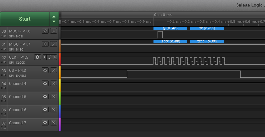
SPI CS is pulled down after 2nd byte. Yes, quite ugly but I did fast :) In fact, the code goes up to the final loop. But I can see no answer on my MISO line! 0x40 means "read register 0" so I should be seeing back the default value which is not 0xFF :) You can see this in my picture below. Again, the slave hardware is checked to work. And even the ISR fires! So let me know your opinions about what I'm doing wrong and have a nice day :)


**Attention** This is a public forum


