This thread has been locked.

If you have a related question, please click the "Ask a related question" button in the top right corner. The newly created question will be automatically linked to this question.

MSP432 not going up to full 48MHz

I'm investigating the various clock sources for the MSP432, and I don't seem to be able to get it to 48MHz using the MSP432 driverlib. I've not tried DRM yet, but I'd like some input here first before I spend time with that.

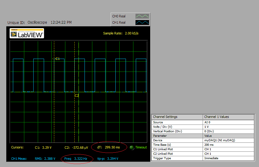
I am simply running the software example cs_hfxt_start.c, and I'm getting something fairly less than 48MHz. I decided to check on the datasheet, and this is found in the CS - CTL2 register value, from running that very code

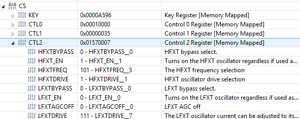
As we can see, the HFXTFREQ value is 101, which according to the datasheet, means a 32Mhz-40Mhz range, where it should be 110, indicating >40MHz.

Is there anything I can do to get around this? 

Thanks,

Paulo

  • Paulo,

    do you just assume that the clock is wrong based on the register settings or did you measure the HSMCLK at P4.4?

    There is

    • msp432p401_cs_03                              Device configuration for operation @ MCLK = DCO = 48MHz

    in the code examples

    http://www.ti.com/lit/zip/slac698

    which runs the device at 48MHz. This example works, so you could have a look at the register settings when using it.

    Dennis

  • Hello,
    I'm not able to check the registers for your suggested program at the moment (only access to Cloud for a few days), but I notice that there's a problem with the 48MHz visually as well.
    In the TI resource explorer, I ran both the programs cs_lxft_start and cs_hxft_start. The lxft worked perfectly, the LED was clearly blinking every .5 seconds.
    The hxft blinks much faster. I even changed the parameter inside the delay function to be 48000000 instead of 24000000 (so the interrupts occur more slowly), but it is still blinking too fast, which does not make sense at all, since the frequency cannot be higher than 48MHz.
    Do you have any idea what could be the problem?
    Thanks,
    Paulo
  • I checked the same problem using the sample code provided with the MSPware. I have no idea what may be happening. LXFT works fine instead of HFXT.

    In the figure shown bellow, we can see the output from P1.0 (LED 1.0) for the cs_hfxt_start.c from MSPWare code example.

    Notice that P1.0 from P1 toggles every 0.3 seconds, when in fact it should toggles every 0.5 seconds.

  • Are you sure you don't get fooled by your scope? You are sampling with 2ksps. Is the scope's bandwidth large enought to sample this signal?
    Your sampling frequency needs to be at least twice the sine frequency of your input signal.

    And as an additional rule of thumb for a digital scope: The sampling rate should be four times larger than it's bandwidth.
  • Sorry. I did not explain properly.

    Paulo Costa said:

    In the TI resource explorer, I ran both the programs cs_lxft_start and cs_hxft_start. The lxft worked perfectly, the LED was clearly blinking every .5 seconds.

    The hxft blinks much faster. I even changed the parameter inside the delay function to be 48000000 instead of 24000000 (so the interrupts occur more slowly), but it is still blinking too fast, which does not make sense at all, since the frequency cannot be higher than 48MHz.

    Do you have any idea what could be the problem?

    resuming...

    The MSPWare provides two code examples, to demonstrate  how to configure properly the clock system MCLK from HFXT and LFXT clock sources respectively. Both set the SysTick interrupt to blink the Launchpad LED every 0.5 seconds using the MCLK clock source, but this is not effectively checked.

    Looking the cs_hfxt_start.c and cs_lfxt_start.c respectively we can see the following settings:

    int main(void)
    {
        /* Halting the Watchdog */
        MAP_WDT_A_holdTimer();
        
        /* Configuring pins for peripheral/crystal usage and LED for output */
        MAP_GPIO_setAsPeripheralModuleFunctionOutputPin(GPIO_PORT_PJ,
                GPIO_PIN3 | GPIO_PIN4, GPIO_PRIMARY_MODULE_FUNCTION);
        MAP_GPIO_setAsOutputPin(GPIO_PORT_P1, GPIO_PIN0);
    
        /* Setting the external clock frequency. This API is optional, but will
         * come in handy if the user ever wants to use the getMCLK/getACLK/etc
         * functions
         */
        CS_setExternalClockSourceFrequency(32000,48000000);
    
        /* Starting HFXT in non-bypass mode without a timeout. Before we start
         * we have to change VCORE to 1 to support the 48MHz frequency */
        MAP_PCM_setCoreVoltageLevel(PCM_VCORE1);
        MAP_FlashCtl_setWaitState(FLASH_BANK0, 2);
        MAP_FlashCtl_setWaitState(FLASH_BANK1, 2);
        CS_startHFXT(false);
    
        /* Initializing MCLK to HFXT (effectively 48MHz) */
        MAP_CS_initClockSignal(CS_MCLK, CS_HFXTCLK_SELECT, CS_CLOCK_DIVIDER_1);
        
        /* Configuring SysTick to trigger at 24000000 (MCLK is 48MHz so this will
         * make it toggle every 0.5s) */
        MAP_SysTick_enableModule();
        MAP_SysTick_setPeriod(24000000);
        MAP_Interrupt_enableSleepOnIsrExit();
        MAP_SysTick_enableInterrupt();
        
         /* Enabling MASTER interrupts */
        MAP_Interrupt_enableMaster();   
    
        while (1)
        {
            MAP_PCM_gotoLPM0();
        }
    }
    
    void systick_isr(void)
    {
        MAP_GPIO_toggleOutputOnPin(GPIO_PORT_P1, GPIO_PIN0);
    }


    int main(void)
    {
        /* Halting the Watchdog */
        MAP_WDT_A_holdTimer();
    
        /* Configuring pins for peripheral/crystal usage and LED for output */
        MAP_GPIO_setAsPeripheralModuleFunctionOutputPin(GPIO_PORT_PJ,
                GPIO_PIN0 | GPIO_PIN1, GPIO_PRIMARY_MODULE_FUNCTION);
        MAP_GPIO_setAsOutputPin(GPIO_PORT_P1, GPIO_PIN0);
    
        /* Setting the external clock frequency. This API is optional, but will
         * come in handy if the user ever wants to use the getMCLK/getACLK/etc
         * functions
         */
        CS_setExternalClockSourceFrequency(32000,48000000);
    
        /* Starting LFXT in non-bypass mode without a timeout. */
        CS_startLFXT(false);
    
        /* Initializing MCLK to LFXT (effectively 32khz) */
        MAP_CS_initClockSignal(CS_MCLK, CS_LFXTCLK_SELECT, CS_CLOCK_DIVIDER_1);
    
        /* Since we are operating at 32khz, we can operating in LF mode */
        MAP_PCM_setPowerMode(PCM_LF_MODE);
    
        /* Configuring SysTick to trigger at 16000 (MCLK is 32khz so this will make
         * it toggle every 0.5s) */
        MAP_SysTick_enableModule();
        MAP_SysTick_setPeriod(16000);
        MAP_Interrupt_enableSleepOnIsrExit();
        MAP_SysTick_enableInterrupt();
    
        /* Enabling MASTER interrupts */
        MAP_Interrupt_enableMaster();
    
        while (1)
        {
            MAP_PCM_gotoLPM0();
        }
    }
    
    void systick_isr(void)
    {
        MAP_GPIO_toggleOutputOnPin(GPIO_PORT_P1, GPIO_PIN0);
    }

    Both codes should result in a LED blinking every 0.5 seconds, but is not what happens in practice, as now we can see in the short video bellow:

    The LFXT seems to work perfectly, but the HFXT not. The source codes shown above are the original sources code examples provided by texas MSPWare. I have not made any changes in them. What could be wrong?

  • OK! Did you route the clock frequency to an output pin already? To check if it is the clock source is running at the desired frequency?
  • Dennis Eichmann said:
    OK! Did you route the clock frequency to an output pin already? To check if it is the clock source is running at the desired frequency?

    I don't have access right now to an oscilloscope and my university is closed for the holiday. But I did another test, but now, using DCO as source clock input for MCLK and then I realized that the problem is still occurring for certain clock speed threshold. In all tests, I kept configuring the SysTick interruption for toggles the LED every 0.5 seconds. The desired result were obtained when the source clock speed falls below a certain threshold. Then, I discovered that the problem isn't the clock system, but the SysTick Period. In the example code provided by Texas MSPWare for HFXT (48MHz) the SysTick period is configured as follows:
    MAP_SysTick_setPeriod(24000000);

    But, the Driver Library Manual indicates that the period value range accepted is between 1 up to 16, 777, 216. I believe this explains why the cc_lfxt_start.c worked fine (MAP_SysTick_setPeriod(16000)) and cc_hfxt_start.c didn't. 

    Apparently I just fooled by the sample code from MSPWare. Although this is not critical, it could be fixed in the next release, but I don't know how inform the developers team.

    Dennis, thank you for your help!

    Best regards.

  • Otavio Augusto Gomes said:

    I don't have access right now to an oscilloscope and my university is closed for the holiday.

    BTW, if logic analyzer with 24 MHz sampling is enough than 5529 LP can be used for this.
    Or, if it is enough just frequency meter up to 50 MHz.
  • Hi,

    Did you find the solution for this?

    I run the example and I toggle the led in the while loop. It seams that the processor is not running at 48MHz at all.

    Thank you for your help

  • Hi! Resurrecting 2 year old threads rarely works. Person you are trying to reach either fixed problem or gave-up but what's important - do not read this forum anymore, did not post anything here for long time. It is always better to start new thread unless there is currently ongoing discussion you can "jump into" with your question.

**Attention** This is a public forum