This thread has been locked.
If you have a related question, please click the "Ask a related question" button in the top right corner. The newly created question will be automatically linked to this question.
Hello community,
I just got myself a MSP430FR5969 Launchpad to get a feeling for the MSP430 µControllers. Now I'm playing around with it a little bit to see how everything works. I have started with switching on the LEDs, to reading buttons, combining everything and now I want to change the brightness of the LED via PWM.
#include <msp430.h> int main(void) { WDTCTL = WDTPW | WDTHOLD; // Stop watchdog timer PM5CTL0 &= ~LOCKLPM5; // Disable the GPIO power-on default high-impedance mode // to activate previously configured port settings P1DIR |= BIT0; // Set P1.0 to output direction P1OUT &= ~BIT0; // Switch LED off P1DIR &= ~BIT1; // Set P1.1 as input P1OUT |= BIT1; // Configure P1.1 for Pull-Up P1REN |= BIT1; // Enable Pull Up of P1.1 P4DIR &= ~BIT5; // Set P4.5 as input P4OUT |= BIT5; // Configure P4.5 for Pull-Up P4REN |= BIT5; // Enable Pull Up of P4.5 TA0CCTL1 = OUTMOD_7; // Reset/Set Mode TA0CTL = TASSEL_2 + MC_1 +TACLR ; // SMCLK / Upmode TA0CCR0 = 100-1; // PWM Frequency 10 kHz TA0CCR1 = 50; // 50% Duty Cycle P1SEL0 |= BIT0; // PWM output to LED P1.0 P1SEL1 &= ~BIT0; while(1) { if(!(P1IN & BIT1)) { TA0CCR1 += 10; } else if(!(P4IN & BIT5)) { TA0CCR1 -= 10; } } }
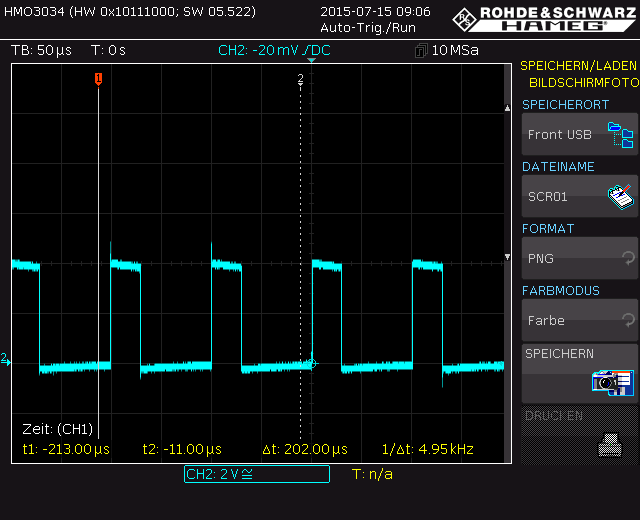
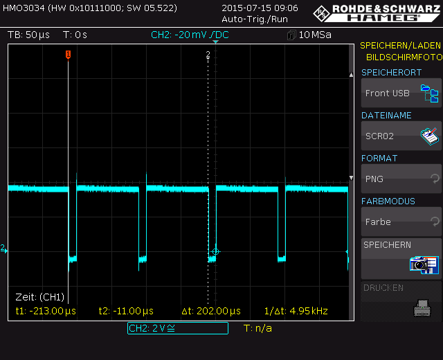
The problem are the last view lines where I try to change the brightness of the LED by pushing a "Up" or "Down" button. After program start the PWM output will be enabled and is running just fine. As soon as I press a button and therefore update the TA0CCR1 register the PWM output will stop and I only measure a permanent high level on the LED.
When I change the last few line to this
while(1) { if(!(P1IN & BIT1)) { TA0CCR1 = 90; } else if(!(P4IN & BIT5)) { TA0CCR1 = 10; } }
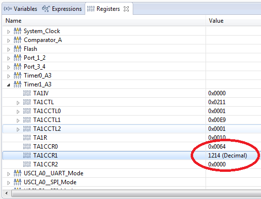
the switching of the brightness works flawlessly. Bright -> Dark -> Bright -> Dark and so on. Trying to reduce the "step size" or working with a variable to change the CCR register does not help. The PWM will crash as soon as I try to set it dynamically. During debugging I can see that the register is updated correctly and not out of range. Still the PWM won't work anymore after the first button press. To make everything worse there are lots of examples in the net which are doing the same thing as I do and change the PWM duty cycle on the fly.
So I ask you what am I doing wrong?
Yours faithfully,
Christopher
while(1) { if(!(P1IN & BIT1)) TA0CCR1 += 10; else if(!(P4IN & BIT5)) TA0CCR1 -= 10; }
One iteration of this loop executes in probably no more than twenty CPU cycles.
At 1 MHz, if you manage to press a button for about a tenth of a second, the addition/subtraction will be executed about five thousand times.
If you want to change the CCR only once per button press, you need to add a check whether the button state has changed, compared to its previous state. (This also requires that you debounce the button signals.)
Hello Mr. Ladisch,
yes of course you have to be careful with the range of the values due to the fast execution of the µC itself. But as I wrote before I have used the debug mode to check the functionality. During debugging I use single step mode and can see that the values for the registers are updated correctly and within working values. Still the PWM will not work. Anyways after some more reading of the datasheet I followed the TI advice to disable to timer while reloading the registers. This way the PWM will work. Still I do not understand why a fixed value will not let the PWM crash and using variables will.
while(1) { if(!(P1IN & BIT1)) { if(TA0CCR1 <= 90) { TA0CCR0 = 0; TA0CCR1 += 10; TA0CCR0 = 100; } } else if(!(P4IN & BIT5)) { if(TA0CCR1 >= 10) { TA0CCR0 = 0; TA0CCR1 -= 10; TA0CCR0 = 100; } } for(j=100;j>0;j--) { __delay_cycles(1000); } }
Christopher,
I have never experienced that the PWM stops when you alter the CCR register. Clemens said the most important thing - you have to make your button read function "human-friendly". For a normal (single) button press, you have to detect and react on the change of the input, not it's current state. You could run a timer that checks the inputs in 10 or 20 ms intervals. If the new state is different from the one you had 10 ms before you can assume that even the worst button is debounced and has now settled and signal a button press.
In the code lines of your opening post you did not check for CCR1 being smaller than CCR0 and of course the duty cycle of a PWM can never extend the frequency, so your output will reside high. Did you measure the pin's voltage level with a normal multimeter? Then you would not recognize if the pin is low for a short time - only an oscilloscope can do that.
You are incrementing +10 each time the microprocessor detects a pressed button. As Clemens said, the micro is very fast and runs over this lines of code thousands of times, even when you press the button only for a short time (from a human point of view). So incrementing +10 to CCR1 happens thousands of times, too.
You only get a valid duty cycle until CCR1 is 100 (as CCR0) which is done in 10 incrementing steps when starting from 0. After that, your duty cycle (CCR1) increments further, but the frequency (CCR0) is still the same, so you have a constant high from CCR1 being higher than CCR0. When CCR1 hits the border of an unsigned 16 bit integer (65535), it rolls over to 0 again.
In your case that means you have less than 1% of your desired frequency-interval where you still have low pulses in between and the rest is all high - compare 0 to 100 against 101 to 65535. Your multimeter won't show this to you because it has some averaging and is too slow for small spikes. You would need an oscilloscope. Furthermore your CCR1 value changes each time CCR1 rolls over, because when it rolls over after the first round, it is (caused by your increment of +10) 65530 plus another 10 which will lead to CCR1 now being 4, then plus 10 it is 14 and so on. This changes again in the next round.
Look at these oscilloscope files:
This is CCR0 == 100 and CCR1 == 30
This is CCR0 == 100 and CCR1 == 90
This is CCR0 == 100 and CCR1 == 100 (look at the little low-pulse)
This is CCR0 == 100 and CCR1 == 100 with a magnification of the small low-pulse - it is exactly 1µs == 1 TA1CLK cycle == 1 SMCLK cycle @ 1MHz
This is CCR0 == 100 and CCR1 == 101 and you can see that now everything is high because CCR1 > CCR0
This is CCR0 == 100 and CCR1 == 0 which leads to everything beeing low
And the following might be interesting for you, too - I have counted the cycle times the microprocessor hits the button check when I press the input button for a very short time, again from a human point of view. I used a G2553 on the MSP-EXP430G2 LaunchPad and my input button was S2 (P1.3). The clock frequency I used is the calibrated 1MHz DCO which also sources the timer without any prescaler. This is the source code:
#include "msp430g2553.h" #include <stdint.h> uint32_t cycle_counter = 0; void main( void ) { WDTCTL = (WDTPW | WDTHOLD); BCSCTL1 = CALBC1_1MHZ; DCOCTL = CALDCO_1MHZ; P1REN |= 0x08; P1OUT |= 0x08; P2SEL |= 0x02; P2DIR |= 0x02; TA1CCR0 = 100; TA1CCR1 = 50; TA1CCTL1 = OUTMOD_7; TA1CTL = (TASSEL_2 | MC_1 | TACLR); while( 1 ) { if( !(P1IN & 0x08) ) { cycle_counter++; TA1CCR1 += 10; } } }
And here is the result for a single click on the button:
As you can see, the short button press caused the variable cycle_counter to be incremented 6670 times which means, your CCR1 was incremented by (6670 * 10). When beginning from 50 we would expect it to be (50 + 66700) == 66750 now, but this extends the range of a normal 16 bit unsigned integer, so what will it be now? It is simple: (66750 - 65535) == 1214
Let's look at CCR1:
There it is.
So you should now start to write some code to detect a single button press, even if the user holds the button down. You could add some sort of repeat functionality for an ongoing press, like adding +10 every 200 ms. But this is up to you.
Hope this helps.
Dennis
Dear Mr Eichmann,
thank you for your detailed explanation. This is of course all known to me and therefore I use the debug mode to ensure that the CCR1 register stays in range. No human can press the button faster than the µC runs its program. In single step mode a pressed button will only execute the increment / decrement routine only once. Much more human friendly.
There you can see that the CCR1 register is for example incremented from it's start value 32h to 3Ch. Same for the single step decrement. 32h to 28h.
Still the PWM signal will be turned in both examples to a permanent high on the port pin. And just like you I have used an oscilloscope to measure the signal.
Since TI is advising itself to stop the counter by setting the CCR0 register to 0 before changing the other CCR registers this is what I'm doing now and this works for me.
**Attention** This is a public forum