This thread has been locked.
If you have a related question, please click the "Ask a related question" button in the top right corner. The newly created question will be automatically linked to this question.
Hi everyone,
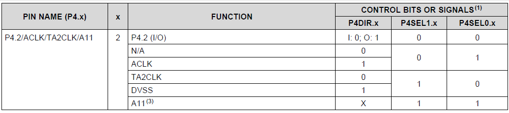
I have searched through the datasheet and the technical reference manual for MSP432 microcontrollers, but I cannot find a way to determine which function is primary, secondary, or tertiary on a particular pin of those microcontrollers. Am I missing something? Or should TI put up an explanation about this?
Best regards,
Dear Clemens,
Thanks for pointing me to the right direction. I was looking for some kind of table, as a quick reference.
I guess we would have to learn the harder way (looking at schematics or trying to remember combinations for those PnSELx.y bits in tables) for now.
Best regards,
Namqn,
the different functions of one pin aren't really numbered as first, second, third, ... function. You could see the increment of PxSEL1 in combination with PxSEL0 as "number", but PxDIR might also seperate one PxSEL1/PxSEL0 setting into two different functions. Look at P4.2, for example:
If you look at P4SEL1 and P4SEL0 as a two bit counter you have
so four different functions determinded by the P4SEL0/P4SEL1 settings, but the setting of P4DIR subdivides the 10b setting into two more functions, so you have five possible settings for this pin (there would be another possible option for 01b, but it is not available here).
Dennis
I really don't think this adequately answers the original question. The Driverlib software manual uses predefined constants GPIO_PRIMARY_MODULE_FUNCTION or GPIO_SECONDARY_MODULE_FUNCTION or GPIO_TERTIARY_MODULE_FUNCTION, and as far as I can find, there is no clear documentation of what exactly this means in the Driverlib Users Guide. You must go find the source code:
void GPIO_setAsPeripheralModuleFunctionInputPin(uint_fast8_t selectedPort,
uint_fast16_t selectedPins, uint_fast8_t mode)
{
uint32_t baseAddress = GPIO_PORT_TO_BASE[selectedPort];
HWREG16(baseAddress + OFS_LIB_PADIR) &= ~selectedPins;
switch (mode)
{
case GPIO_PRIMARY_MODULE_FUNCTION:
HWREG16(baseAddress + OFS_LIB_PASEL0) |= selectedPins;
HWREG16(baseAddress + OFS_LIB_PASEL1) &= ~selectedPins;
break;
case GPIO_SECONDARY_MODULE_FUNCTION:
HWREG16(baseAddress + OFS_LIB_PASEL0) &= ~selectedPins;
HWREG16(baseAddress + OFS_LIB_PASEL1) |= selectedPins;
break;
case GPIO_TERTIARY_MODULE_FUNCTION:
HWREG16(baseAddress + OFS_LIB_PASEL0) |= selectedPins;
HWREG16(baseAddress + OFS_LIB_PASEL1) |= selectedPins;
break;
}
From this it is evident that primary means PASEL0 is 1 and PASEL1 is 0. (01)
Also that secondary means that PASEL0 is 0 and PASEL1 is 1. (10)
Also that tertiary means that PASEL0 and PASEL1 are both 1. (11)
From this point you need to look at the data sheet, section 6.10.x, and see what the PASELi (PxSELi) bits need to be set to for your desired function.
It appears that the order functions are listed in the datasheet is default, usually gpio (00)/primary(01)/secondary(10)/tertiary(11). This is shown in pinouts, and in the tables in Section 6.10. I only did spot checks, but it appears this will give the quickest way to figure out whether it is primary, secondary or tertiary. In summary, the first listing on the pin is the default (not primary, secondary or tertiary); the second is primary; the third is secondary; and the fourth is tertiary.
Rob
Well this is correct. SPI or I2C (or UART for some pins) is selected with a bit in the USCI module. For the general pin-function you only select the USCI option first by setting the proper PxSEL bits.
Dennis
**Attention** This is a public forum