This thread has been locked.
If you have a related question, please click the "Ask a related question" button in the top right corner. The newly created question will be automatically linked to this question.
I am at my wits end!!
I think I have everything set correctly, yet when I send characters from a SI Labs CP2104-EK (USB to Serial converter) to my 5438 no interrupt is generated. I am using RealTerm for sending from the PC, so I can vary the baud rate and how the data gets sent.
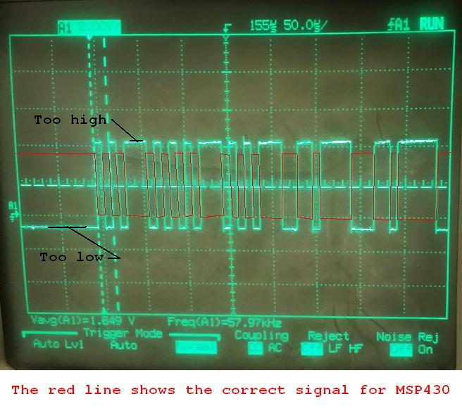
This is what I send from the USB converter.
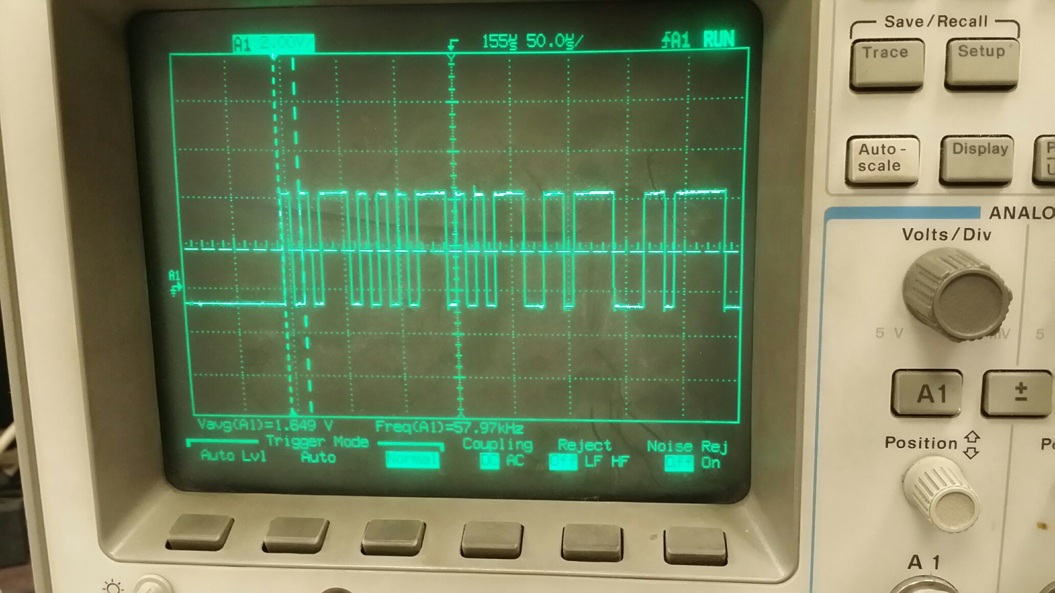
This is what I get back from the 5438, yet there is no interrupt.
Here is what I have in code.
Initialize
void UART3_Init (void) @ "CODE"
{
WDTCTL = WDTPW + WDTHOLD; // Stop WDT
UCA3CTL1 |= UCSWRST; // **Put state machine in reset**
UCA3CTL1 |= UCSSEL_1; // ACLK
UCA3BR0 = 0x09; ; // = 1.125MHz 115200 (see User's Guide)
UCA3BR1 = 0x00; // 1MHz 115200
UCA3MCTL |= UCBRS_6 + UCBRF_0; // Modulation
UCA3CTL1 &= ~UCSWRST; // **Initialize USCI state machine**
UCA3IE |= UCRXIE; // Enable USCI_A3 RX interrupt
__bis_SR_register(GIE); // interrupts enabled
__delay_cycles(10000);
}
ISR.c
#pragma location = "CODE"
#pragma vector=USCI_A3_VECTOR
__interrupt void USCI_A3_ISR(void)
{
switch(__even_in_range(UCA3IV,4))
{
char temp;
case 0:
break; // Vector 0 - no interrupt
case 2: // Vector 2 - RXIFG
//char temp;
temp = UCA3RXBUF;
some code is executed in the ISR but the ISR never gets called.
case 4: // Vector 4 - TXIFG
__delay_cycles(5000);//(5000); // Add small gap between TX'ed bytes
UCA3TXBUF = TXmsg[pmsg++];
if(nmsg==pmsg) UCA3IE &= ~UCTXIE; // disable USCI_A0 TX buffer
break;
default:
break;
}
Using IAR in debug mode I put a halt at the switch(__even_in_range(UCA3IV,4)) but no interrupt is generated.
The code is identical to the A0 UART and that works fine!
Thanks in advance for your help.
Dennis,
Thanks for taking a look.
I have been using UART0 for a long time with great results. I am now trying to get UART3 going so I have an additional port to talk to the outside world.
the A0 port is going through a CP2110 located on my board to interface to the USB.
Port A3 is supposed to go through a CP2104 external to my board.
I have jumpered P3.5 (A0_URX) to P10.5 (A3_URX)on my board. I did this to use the same data that is coming in through my 2110 and use it to trigger the A3 interrupt.
Initilization
SetPort3;
#define SetPort3 { P3SEL = 0xB6; P3OUT = 0x40; P3DIR = 0x49; P3REN = 0x00;}
SetPort10;
#define SetPort10 { P10SEL = 0xf0; P10OUT = 0x00; P10DIR = 0x0A; P10REN = 0x00;}
UART0_Init();
UART3_Init();
/-----------------------------------------------------------------------------
// UART0_Init
//-----------------------------------------------------------------------------
void UART0_Init (void) @ "XX25_CODE"
{
WDTCTL = WDTPW + WDTHOLD; // Stop WDT
UCA0CTL1 |= UCSWRST; // **Put state machine in reset**
UCA0CTL1 |= UCSSEL_1; // ACLK
UCA0BR0 = 0x0d; //0x0D; //9 = 1MHz 115200 (see User's Guide)55 = 19200
UCA0BR1 = 0x00; //0; // 1MHz 115200
UCA0MCTL = 0xf3;//UCA0MCTL |= UCBRS_1 + UCBRF_0; //UCBRF_10 // Modulation UCBRSx=1, UCBRFx=0
UCA0CTL1 &= ~UCSWRST; // **Initialize USCI state machine**
UCA0IE |= UCRXIE; // Enable USCI_A0 TX/RX interrupt
__bis_SR_register(GIE); // interrupts enabled
__delay_cycles(10000);
}
void UART3_Init (void) @ "XX25_CODE"
{
WDTCTL = WDTPW + WDTHOLD; // Stop WDT
UCA3CTL1 |= UCSWRST; // **Put state machine in reset**
UCA3CTL1 |= UCSSEL_1; // ACLK
UCA3BR0 = 0x9; // = 1.125MHz 115200 (see User's Guide)
UCA3BR1 = 0x00; // 1MHz 115200
UCA3MCTL |= UCBRS_6 + UCBRF_0; // Modulation
UCA3CTL1 &= ~UCSWRST; // **Initialize USCI state machine**
UCA3IE |= UCRXIE; // Enable USCI_A3 RX interrupt
__bis_SR_register(GIE); // interrupts enabled
__delay_cycles(10000);
}
I can step through the code during initialize and I know that UCA3 is getting initialized.
I then start up my external GUI that is sending EE1A15C3 and expecting a response from the MSP.
UART A0 does respond but there is no interrupt for UART A3.
If I halt the IAR I will get errors on UCBRK and UCOE . and the UCA3RXBUF = 0x00, but no interrupt
ISR code is:
//------------------------------------------------------------------------------
#pragma location = "COMMO_RX"
#pragma vector=USCI_A0_VECTOR
__interrupt void USCI_A0_ISR(void)
{
switch(__even_in_range(UCA0IV,4))
{
char temp;
case 0:
break; // Vector 0 - no interrupt
case 2: // Vector 2 - RXIFG
//char temp;
temp = UCA0RXBUF;
switch (msgstatus)
{
case (none) :
if(temp==0xEE)
{
msgstatus = cmnd;
RXmsg[0] = temp;
}
break;
case (cmnd) :
RXmsg[1] = temp;
if((temp==0x1C)||(temp==0x1D)||(temp==0x22)||(temp==0x24)||(temp==0x2A))
{
msgstatus = dataln;
cnt = 2;
}
else if(temp == 0x2B)
{
msgstatus = var;
lngth = 0;
cnt = 2;
}
else if(temp == 0x13) //set output voltage
{
msgstatus = var;
lngth = 0; cnt = 2;
}
else if(upgrade && temp==0x26)
{
//UGptr = UGRAM_LOWER;
UGptr=__segment_begin("NEW_CODE");
UGcnt = 1;
msgstatus = UGmsg;
}
else
{
msgstatus = crc1;
}
break;
case(crc1) :
RXmsg[2] = temp;
msgstatus = crc2;
break;
case (crc2) :
RXmsg[3] = temp;
cnt = 4;
verify();
break;
case (ack) :
if(temp==0x06) msgstatus = none;
break;
case (dataln) :
RXmsg[2] = temp;
lngth = temp;
cnt++;
msgstatus = var;
break;
case (var) :
{
RXmsg[cnt++] = temp;
if(cnt>(lngth + 5)) verify();
else if((RXmsg[1] == 0x2B) && (cnt > 4)) verify();
else if((RXmsg[1] == 0x13) && (cnt > 4)) verify();
}
break;
case (UGmsg) :
*UGptr++ = temp;
UGcnt++;
if(UGcnt > 519)
verifyUG();
break;
default :
msgstatus = none;
break;
}
break;
case 4: // Vector 4 - TXIFG
__delay_cycles(5000);//(5000); // Add small gap between TX'ed bytes
UCA0TXBUF = TXmsg[pmsg++];
if(nmsg==pmsg) UCA0IE &= ~UCTXIE; // disable USCI_A0 TX buffer
break;
default:
break;
}
}
The code for the A3 is identical to the A0 (of course it says A3) with the exception of where it is placed in the linker.
//------------------------------------------------------------------------------
#pragma location = "USCI_B0"
#pragma vector=USCI_A3_VECTOR
__interrupt void USCI_A3_ISR(void)
{
switch(__even_in_range(UCA3IV,4))
{
char temp;
case 0:
break; // Vector 0 - no interrupt
case 2: // Vector 2 - RXIFG
//char temp;
temp = UCA3RXBUF;
switch (msgstatus)
{
case (none) :
if(temp==0xEE)
{
msgstatus = cmnd;
RXmsg[0] = temp;
}
break;
case (cmnd) :
RXmsg[1] = temp;
if((temp==0x1C)||(temp==0x1D)||(temp==0x22)||(temp==0x24)||(temp==0x2A))
{
msgstatus = dataln;
cnt = 2;
}
else if(temp == 0x2B)
{
msgstatus = var;
lngth = 0;
cnt = 2;
}
else if(temp == 0x13) //set output voltage
{
msgstatus = var;
lngth = 0; cnt = 2;
}
else if(upgrade && temp==0x26)
{
//UGptr = UGRAM_LOWER;
UGptr=__segment_begin("NEW_CODE");
UGcnt = 1;
msgstatus = UGmsg;
}
else
{
msgstatus = crc1;
}
break;
case(crc1) :
RXmsg[2] = temp;
msgstatus = crc2;
break;
case (crc2) :
RXmsg[3] = temp;
cnt = 4;
verifyA3();
break;
case (ack) :
if(temp==0x06) msgstatus = none;
break;
case (dataln) :
RXmsg[2] = temp;
lngth = temp;
cnt++;
msgstatus = var;
break;
case (var) :
{
RXmsg[cnt++] = temp;
if(cnt>(lngth + 5)) verifyA3();
else if((RXmsg[1] == 0x2B) && (cnt > 4)) verifyA3();
else if((RXmsg[1] == 0x13) && (cnt > 4)) verifyA3();
}
break;
case (UGmsg) :
*UGptr++ = temp;
UGcnt++;
if(UGcnt > 519)
verifyUG();
break;
default :
msgstatus = none;
break;
}
break;
case 4: // Vector 4 - TXIFG
__delay_cycles(5000);//(5000); // Add small gap between TX'ed bytes
UCA3TXBUF = TXmsg[pmsg++];
if(nmsg==pmsg) UCA3IE &= ~UCTXIE; // disable USCI_A0 TX buffer
break;
default:
break;
}
}
If I have left anything out please let me know. The entire code it too much to download here. We have been using this for several years and it has ~ 12 .C files and a couple ASM files also.
Thanks again for helping.
Gerry
**Attention** This is a public forum