- Ask a related questionWhat is a related question?A related question is a question created from another question. When the related question is created, it will be automatically linked to the original question.
Hello everyone
I am working on a project which needs ADC works in max frequency.
I configure ADC work with DMA.
ADC Setting:
clk: 25M using DCO
mode: repeat-single-channel and automatic mode
hold time : 8 cycles
conversion time: 16 cycles
DMA setting:
work in PINGPONG MODE, transfer 256 data each time, data length is 16 bits, triggered by ADC14
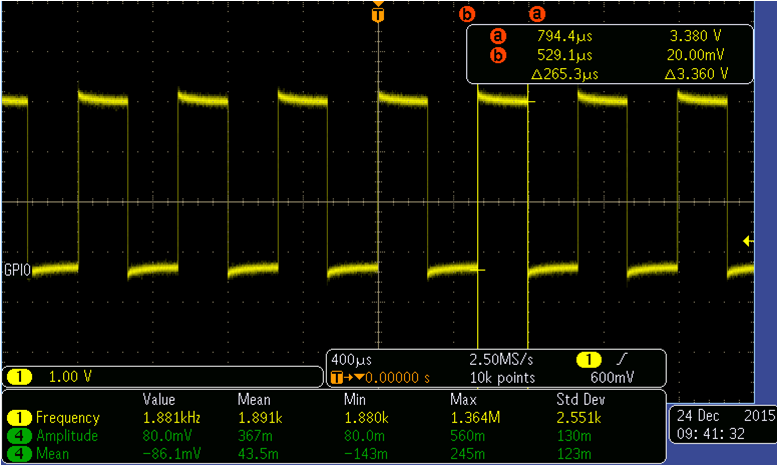
In the DMA interrupt handler, i will toggle a gpio to measure duration of 2 DMA transfer.
I got the result below. It seems that it takes ADC14 265us to generate 256 samples and not expected 256us.
Any comments to my experiment?
Thank you.
**Attention** This is a public forum