


Other Parts Discussed in Thread: MSP-FET, MSP-EXP430FR5739
Dear All,
I am sorry if this question has already been posted. I have found some threads with a similar question, but I have been unable to solve my problem.
I recently purchased a MSP-FET tool to program the MSP-EXP430FR5739 and measure power consumption. I have followed the MSP-FET user's guide to install the hardware in my machine and connected the MSP-FET to the experimenter board as follows (see also image):
| MSP-FET | MSP-EXP430FR5739 |
| TDD/TDI (Pin 1) | RST/NMI/SBWTDIO (Pin 20 --> TP15) |
| TCK (Pin 7) | TEST/SBWTCK (Pin19 --> TP14) |
| VCC_TOOL (Pin 2) | MSP_PWR jumper pin |
| GND (Pin 9) | GND jumper pin |

Please notice that I have disconnected the eZ-430 programmer/debugger (J3 jumpers).
I am using Code Composer Studio version 6.1.1.00022 (latest update), installed on a Windows 8.1 (virtual machine).
When connecting the MSP-FET, I can see it is correctly installed in Control Panel, Device Manager, Ports (COM & LPT), where:
- MSP Application UART1 (COM5)
- MSP Debug Interface (COM6)
Just in case, I can program the experimenter board through the eZ-430 programmer/debugger with no problems.
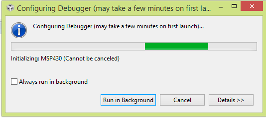
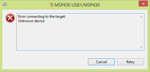
The problem is that, when pressing the debug button, CCS configures the debugger (figure 2) and then it shows the following error message (figure 3):
I suspected it was a problem with the wiring (as shown in the figure 1), so I checked all the connections and even tried a different configuration. Also, as suggested in some other link, I externally powered the experimenter board (3.3 V DC), and at least I could see how the board started working (as expected), as this wasn't happening just connecting the board to MSP-FET.
I hope all this information helps guess what I am possibly doing wrong. I would appreciate any help at your earliest convenience. Many thanks
Best wishes,
David

