This thread has been locked.

If you have a related question, please click the "Ask a related question" button in the top right corner. The newly created question will be automatically linked to this question.

MSP-GANG DLL porting issues from MSP-GANG430 DLL using Wrapper

Other Parts Discussed in Thread: MSP-GANG, MSP430F5435, MSP-FET

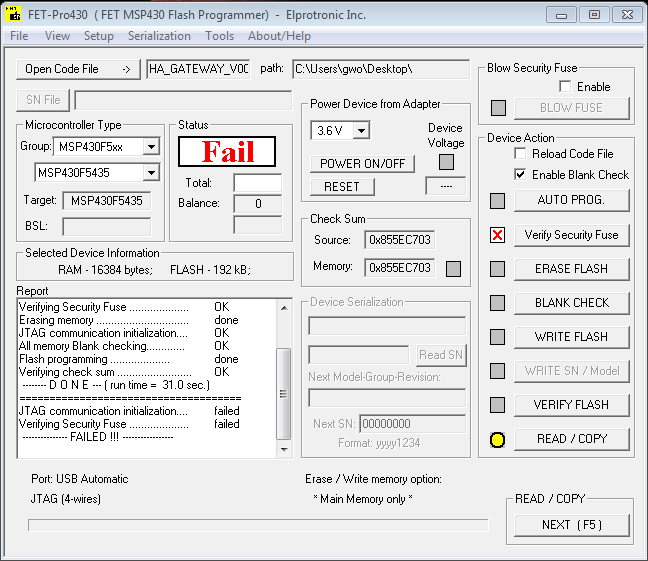
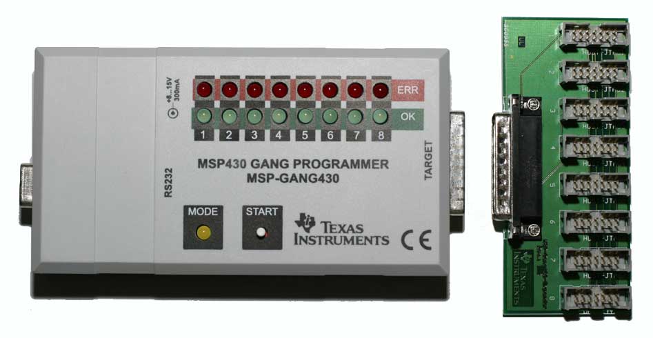
I have been using the previous programmer for years with our custom PC software to program.  I purchased the new MSP-GANG hoping for an easy update.  I followed the directions on page 73 of the guide.  I copied over Gang430.dll, Gang430.ini and MSP-GANG.dll to the program directory.  Using the new MSP-Gang I get the error #23 about failed MCU Initialization.  

Is there some step I am missing?

Thanks,

  • Hi Matt,

    Thanks for posting. For your custom PC program, is it written in C or some other language? In addition, when you did your test, did you also rebuild your software with it pointing to/including the new Gang430.dll etc instead of the old version? We include also some examples for using the wrapper DLL with the MSP-GANG software installation that you might find helpful - look under MSP-GANG/Examples/Wrapper to find some C and C++ examples using the wrapper DLL.

    Regards,
    Katie

  • I just deleted our old Gang430.dll and replaced it with the new one provided.
  • Hi Matt,

    To rule out hardware, can you try programming your board once using the MSP-GANG GUI? This will also serve to make sure you have the latest MSP-GANG firmware version downloaded into the MSP-GANG. We want to make sure the connections between the MSP-GANG and your board are all correct.

    Regards,
    Katie
  • I used the MSP-GANG GUI to check the firmware. Currently it says MSP-Gang A430: 01.02.05.00
  • Were you able to read or program the device using the MSP-GANG GUI? This would be to check that the hardware connections between your device and the MSP-GANG are correct.

    Regards,
    Katie
  • I get the same error 23 if I try to program, erase or read.
  • Hi Matt,

    Thanks for doing that test! That indicates that it is likely not just a software issue with using the wrapper DLL, or else the MSP-GANG GUI should have worked. It is more likely that there is a hardware connection issue.

    Can you provide the following information so that we can help debug your issue:

    JTAG connection questions:

    • What MSP430 device are you programming
    • Are you using a TI target board, or your own custom board?
    • If it's you're own custom board, can you also provide information about your JTAG connections between the MSP-GANG and the MSP device? (schematic snippet?)
    • What R/C combination is on the reset line?
    • You may want to try lowering the value of the cap on the RST line to see if this helps (especially with long traces or cables for RST connection to GANG).
    • Can you take a screenshot of the MSP-GANG GUI so I can see your settings that were used for your test with the GUI.

    Signal path questions:

    • Do you use the provided splitter board from the MSP-GANG and connect to the sockets on there?
    • Do you use the provided ribbon cables to connect to a 14-pin header on your board, or do you use some sort of adaptor or other cable to connect to your board? Can you comment on how long the signal path is from the MSP-GANG to your device on the board (including all cables adapters etc)?

    The reason I'm asking these types of questions, is that there is a limit on the maximum length of the signal path between the MSP device and the MSP-GANG for reliable operation (see www.ti.com/lit/pdf/slau358 section 1.3 there is a note about this).

    Regards,

    Katie

  • http://imgur.com/a/x02rI

    http://imgur.com/a/EiZxc

    This is the setup I am working with. Our custom board with a MSP430F5435 on it and the adapter board inside the white box. We have used this setup for 6+ years to program our boards using the previous programmer, www.ti.com/.../msp-gang430.jpg ,with no issues. As far as I know the pinout on both is the same so that shouldn't be an issue. I don't have access to a schematic right now. But I know the previous setup works fine using the FET-Pro430 GUI and our custom GUI to program with.

    Thanks,
  • Hi Matt,

    Unfortunately, without knowing the hardware connection setup, it will be very difficult to debug error 23, because that error indicates a connection issue. I know that your hardware was working with the old programmer, so it could be that a setting is wrong when using MSP-GANG compared to the hardware on your board. But for that we will need the information about how the device is powered and what JTAG vs SBW connections are made between the device and the MSP-GANG so that we can choose the correct settings. Please let me know if you'd be able to find the schematic or someone who knows about the design of the board you are trying to program and relevant info about that box you are using between the board and the MSP-GANG.

    Regards,
    Katie

  • Hello Matt,

    Can you check a couple of things for me?  On the GUI, what is the interface option set to?  should be SBW.

    Just in case, what is the target power supply current set to?

    Thanks.
    Marc

  • http://imgur.com/a/f52RA

    Here is the schematic. Vcc is 3.3V on the adapter board.

  • Hi Matt,

    Thanks for posting the schematic of the connections. Please note that it is possible to post images directly in your posts if you don't want to have to use imgur ().

    Note that Marc was off-base - he assumed you were using SBW but your schematic shows you must be using JTAG.

    I see that the 14-pin header appears to be mirrored/rotated in the schematic  - e.g. it is showing TDO/TDI on pin 14 on  your schematic instead of pin 1.

    Is the header that you have for the programmer actually keyed, or could the cable be connected in the wrong direction?

    I'm also concerned about all this extra circuitry on the RST line. The entry sequence for JTAG/SBW is very timing sensitive and we even recommend a specific R/C pair to go on that line (47k pullup R with no larger than ~1-2.2nF cap to GND) - see the figure 2-1 diagram above (from )  I'd be concerned that the difference could be that the MSP-GANG is more timing-sensitive than MSP-GANG430UIF, and the design of this is already violating the R/C pair we recommend in the hardware tools user's guide for all of our programmers. We can't guarantee that our tools will work with a configuration other than what is in the diagram above, as that is what they are tested with.

    Finally, when you mention 3.3V is that being supplied by the MSP-GANG (which is what your pin connection indicates would be correct) or is it supplied by something else (like something in that white box?)

    Regards,

    Katie

  • The header is keyed.
    The power in the white box is supplied by a 3.3V wall adapter.
    I will try the new R/C pair.

    Thanks,
  • Matt,

    The white box is powered by a 3.3V wall adapter but do you know if that box is what is supplying the power to the MSP, or is the MSP-GANG what is supplying the power to the MSP? This would determine your MSP-GANG setting and also which pin should be used for VCC on the JTAG header.

    Regards,
    Katie
  • It can be either. Right now it is set up to be powered via VCC Tool. In the GUI I have Target's power Supply set to Supplied by Programmer, 3.2V, max 50mA, and Vcc Settle Time 2.0s. Vcc On.
  • I ended up making the modifications you suggested and I could program it fine with the built in GUI over and over.  So that is good.  

    I did notice that after programming it with our legacy GUI and the new dll files that it seems to blow the security fuse after programming it.  Anytime we try to program afterwards we get a Error #23 again.  There is no option to even select blow security fuse in our GUI.  Any ideas why we are suddenly blowing the security fuse or is there something else going on?

    Thanks,

  • Hi Matt,

    Error 23 doesn't necessarily mean that the fuse was blown. It could also mean something is not set up correctly, or maybe your part has bad code in it that is causing it to reset quickly or something.

    When you say you use your legacy GUI with the new dll files - by legacy GUI do you mean a program that your company developed that used the old DLL but has a GUI interface? Or do you mean the old GUI that was previously provided by TI?

    If it's a custom program that you made - could you tell what program is used (e.g. c++ visual studio, etc) and the sequence of commands used in the software?

    After you get error 23, if you try to use the MSP-GANG + the new GUI are you able to get back into the part or no?

    Regards,
    Katie
  • Katie Pier said:
    When you say you use your legacy GUI with the new dll files - by legacy GUI do you mean a program that your company developed that used the old DLL but has a GUI interface? Or do you mean the old GUI that was previously provided by TI?

    Our own program software that used the old DLL with a GUI interface.

    Katie Pier said:
    If it's a custom program that you made - could you tell what program is used (e.g. c++ visual studio, etc) and the sequence of commands used in the software?

    C sharp with visual studio I think.  Haven't dove into the source yet.

    Katie Pier said:
    After you get error 23, if you try to use the MSP-GANG + the new GUI are you able to get back into the part or no?

    No, on every programmer I try after that I get the error.  

    I connected it to a MSP430 USB-Debug-Interface MSP-FET430UIF to view the secure fuse in their GUI.  You can see the first program went through fine because it hasn't been programmed with our custom GUI with new DLLs and new programmer.  But when in I put in the device that is non-responsive, aka the one that fails at initialization, I get this.

  • mattg said:

    No, on every programmer I try after that I get the error.  

    I connected it to a MSP430 USB-Debug-Interface MSP-FET430UIF to view the secure fuse in their GUI.  You can see the first program went through fine because it hasn't been programmed with our custom GUI with new DLLs and new programmer.  But when in I put in the device that is non-responsive, aka the one that fails at initialization, I get this.


    If your program (during execution) on MSP430F5435 doesn't write anything to protected BSL flash memory segment where soft JTAG fuse value is located, than this is due to bad code.

  • Hi Matt,

    Do you know what addresses your program writes to in the device? Does it write to the BSL area of flash?

    In addition, it could just be a bad code load - in that case, the best way to recover a failing part will likely be to use the BSL to erase the device - do you know if you have access to the BSL pins on this part? The default factory BSL uses the pins listed in the datasheet www.ti.com/.../msp430f5435 table 6-3 BSL Pin Requirements and Functions - do you have access to these pins on your device? If so I could walk you through connecting the MSP-GANG or MSP-FET (not MSP-FET430UIF though) to erase the device using the BSL to see if you can then get back into the part.

    As for why this happens in the first place - it would be really helpful to know the sequence of commands called by your custom DLL project. Then we can check what it is doing.

    Regards,
    Katie
  • Katie Pier said:

    In addition, it could just be a bad code load - in that case, the best way to recover a failing part will likely be to use the BSL to erase the device

    BTW, I found that device locked due to bad code (fuse blow reported) can be unlocked (without BSL) by continuing SBW / JTAG forced execution, few times, until device become alive again. And I implemented this in my flasher. Of course this is related only to bad code, not to situation when fuse is really "blown".
    .
    C:\msp430>flash -forced -e

    Found SBW+ at COM4

    Get Device
    # JTID Fuse
    0  91 Blown
    Error 101: Syncronization problem.
    Warnning: SBW+ PIO connection does not exist.

    Erase
    Error 107: SBW+ PIO connection does not exist.

    Release Device

    C:\msp430>flash -forced -e

    Found SBW+ at COM4

    Get Device
    # JTID Fuse Device Core Hard Soft LotWafer DieX DieY
    0  91   OK   3180  1104  12   12  013BB046 0D00 1E00

    Erase
    Time: 37 ms

    Release Device

    Total Time: 141 ms

    C:\msp430>

  • Hi Matt,

    Are you still stuck, or were you able to get something working? Is there more I can do to help - I think I would need to know the sequence of commands you were using in your custom DLL project to be able to give you further guidance.

    Regards,
    Katie
  • Hi,

    On a whim I ordered a Chinese USB version of the old programmer as the other one was out of stock everywhere. It was a straight up replacement. I never got the msp-gang working, but that wasn't top level problem I was trying to solve.

    Thanks,

**Attention** This is a public forum