This thread has been locked.

If you have a related question, please click the "Ask a related question" button in the top right corner. The newly created question will be automatically linked to this question.

MSP430FR5969: MSP430FR5969 I2C Configuration and Testing

Part Number: MSP430FR5969

Hello,

I'm currently trying to configure the MSP430FR5969 to read from a Si1133. Communication is to be done through I2C.

My difficulty is with the proper order of configuration for this interface. From what I've read (through other discussions and datasheets), I should be able to make use of  eusci_b_i2c and drivelib packages.

The user in this thread is more or less trying to accomplish the same thing.

This is how I see the process working from the Master side:

  1. Initialize GPIO pins (SDA, SCL)
  2. Initialize Master parameters
  3. Initialize Master
  4. Set the Slave Address
  5. Set the mode (Transmit in this case)
  6. Enable I2C block
  7. Transmit Data
  8. Stop

The the 'Transmit Data' Part  is what I am questioning. 

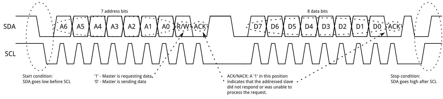
According to the Si1133 Datasheet, a simple write sequence consists of the following order of commands (from the Master):

  1. Start
  2. Send Slave Address
  3. Set Write
  4. Receive ACK
  5. Send Register Adress
  6. Receive ACK
  7. Send Data
  8. Receive ACK
  9. Send Stop

Now the eusci_b_i2c library provides functions that send a START, then DATA, then STOP, all in one call. But I don't believe that's what I want to do here.

As a starting point, all I would like to do is send the SLAVE Address, then read the ACK. Where exactly is the ACK sent? I imagine it's flag, just unsure of what one.
Perhaps using getInterruptStatus is a way to check?
Also, is it possible to check if the ACK was received while in Debug?

Feel free to ask for any clarification. For context, I'm a student trying to learn bare-metal C.

Thank you

  • Hi Rudy,

    Thank you for your detailed post and context.

    To determine if the Slave did not acknowledge the transmitted address, the not-acknowledge interrupt flag UCNACKIFG is set, which can be checked during debugging. The Master must react with either a STOP condition or a repeated START condition. When using the MSP430 in Master Receiver mode, refer to Section 26.3.5.2.2 and Figure 26-13 in the User's Guide for more details.

    For the ACK,  you could think of it as a flag. Since I2C is an open-drain protocol, the Slave will pull down SDA to alert the Master that it has acknowledged the address or data.

    For a bare-metal C code example, take a look at msp430fr59xx_euscib0_i2c_10.c. In the USCI_B0_ISR, you should be able to put a break point on Line 124 under "case USCI_I2C_UCNACKIFG". If this break point is never reached, the Slave should be acknowledging properly.

    msp430fr59xx_euscib0_i2c_10.c

    /* --COPYRIGHT--,BSD_EX
     * Copyright (c) 2012, Texas Instruments Incorporated
     * All rights reserved.
     *
     * Redistribution and use in source and binary forms, with or without
     * modification, are permitted provided that the following conditions
     * are met:
     *
     * *  Redistributions of source code must retain the above copyright
     *    notice, this list of conditions and the following disclaimer.
     *
     * *  Redistributions in binary form must reproduce the above copyright
     *    notice, this list of conditions and the following disclaimer in the
     *    documentation and/or other materials provided with the distribution.
     *
     * *  Neither the name of Texas Instruments Incorporated nor the names of
     *    its contributors may be used to endorse or promote products derived
     *    from this software without specific prior written permission.
     *
     * THIS SOFTWARE IS PROVIDED BY THE COPYRIGHT HOLDERS AND CONTRIBUTORS "AS IS"
     * AND ANY EXPRESS OR IMPLIED WARRANTIES, INCLUDING, BUT NOT LIMITED TO,
     * THE IMPLIED WARRANTIES OF MERCHANTABILITY AND FITNESS FOR A PARTICULAR
     * PURPOSE ARE DISCLAIMED. IN NO EVENT SHALL THE COPYRIGHT OWNER OR
     * CONTRIBUTORS BE LIABLE FOR ANY DIRECT, INDIRECT, INCIDENTAL, SPECIAL,
     * EXEMPLARY, OR CONSEQUENTIAL DAMAGES (INCLUDING, BUT NOT LIMITED TO,
     * PROCUREMENT OF SUBSTITUTE GOODS OR SERVICES; LOSS OF USE, DATA, OR PROFITS;
     * OR BUSINESS INTERRUPTION) HOWEVER CAUSED AND ON ANY THEORY OF LIABILITY,
     * WHETHER IN CONTRACT, STRICT LIABILITY, OR TORT (INCLUDING NEGLIGENCE OR
     * OTHERWISE) ARISING IN ANY WAY OUT OF THE USE OF THIS SOFTWARE,
     * EVEN IF ADVISED OF THE POSSIBILITY OF SUCH DAMAGE.
     *
     *******************************************************************************
     *
     *                       MSP430 CODE EXAMPLE DISCLAIMER
     *
     * MSP430 code examples are self-contained low-level programs that typically
     * demonstrate a single peripheral function or device feature in a highly
     * concise manner. For this the code may rely on the device's power-on default
     * register values and settings such as the clock configuration and care must
     * be taken when combining code from several examples to avoid potential side
     * effects. Also see www.ti.com/grace for a GUI- and www.ti.com/msp430ware
     * for an API functional library-approach to peripheral configuration.
     *
     * --/COPYRIGHT--*/
    //******************************************************************************
    //  MSP430FR59xx Demo - eUSCI_B0 I2C Master RX multiple bytes from MSP430 Slave
    //
    //  Description: This demo connects two MSP430's via the I2C bus. The master
    //  reads 5 bytes from the slave. This is the MASTER CODE. The data from the slave
    //  transmitter begins at 0 and increments with each transfer.
    //  The USCI_B0 RX interrupt is used to know when new data has been received.
    //  ACLK = n/a, MCLK = SMCLK = BRCLK =  DCO = 1MHz
    //
    //    *****used with "MSP430FR59xx_euscib0_i2c_11.c"****
    //
    //                                /|\  /|\
    //               MSP430FR5969      10k  10k     MSP430F5969
    //                   slave         |    |        master
    //             -----------------   |    |   -----------------
    //           -|XIN  P1.6/UCB0SDA|<-|----+->|P1.6/UCB0SDA  XIN|-
    //            |                 |  |       |                 | 32kHz
    //           -|XOUT             |  |       |             XOUT|-
    //            |     P1.7/UCB0SCL|<-+------>|P1.7/UCB0SCL     |
    //            |                 |          |             P1.0|--> LED
    //
    //   P. Thanigai
    //   Texas Instruments Inc.
    //   Feb 2012
    //   Built with CCS V5.5
    //******************************************************************************
    #include <msp430.h>
    
    volatile unsigned char RXData;
    
    int main(void)
    {
      WDTCTL = WDTPW | WDTHOLD;
    
      // Configure GPIO
      P1OUT &= ~BIT0;                           // Clear P1.0 output latch
      P1DIR |= BIT0;                            // For LED
      P1SEL1 |= BIT6 | BIT7;                    // I2C pins
    
      // Disable the GPIO power-on default high-impedance mode to activate
      // previously configured port settings
      PM5CTL0 &= ~LOCKLPM5;
    
      // Configure USCI_B0 for I2C mode
      UCB0CTLW0 |= UCSWRST;                     // Software reset enabled
      UCB0CTLW0 |= UCMODE_3 | UCMST | UCSYNC;   // I2C mode, Master mode, sync
      UCB0CTLW1 |= UCASTP_2;                    // Automatic stop generated
                                                // after UCB0TBCNT is reached
      UCB0BRW = 0x0008;                         // baudrate = SMCLK / 8
      UCB0TBCNT = 0x0005;                       // number of bytes to be received
      UCB0I2CSA = 0x0048;                       // Slave address
      UCB0CTL1 &= ~UCSWRST;
      UCB0IE |= UCRXIE | UCNACKIE | UCBCNTIE;
    
      while (1)
      {
        __delay_cycles(2000);
        while (UCB0CTL1 & UCTXSTP);             // Ensure stop condition got sent
        UCB0CTL1 |= UCTXSTT;                    // I2C start condition
    
        __bis_SR_register(LPM0_bits | GIE);     // Enter LPM0 w/ interrupt
      }
    }
    
    #if defined(__TI_COMPILER_VERSION__) || defined(__IAR_SYSTEMS_ICC__)
    #pragma vector = USCI_B0_VECTOR
    __interrupt void USCI_B0_ISR(void)
    #elif defined(__GNUC__)
    void __attribute__ ((interrupt(USCI_B0_VECTOR))) USCI_B0_ISR (void)
    #else
    #error Compiler not supported!
    #endif
    {
      switch(__even_in_range(UCB0IV, USCI_I2C_UCBIT9IFG))
      {
        case USCI_NONE:          break;         // Vector 0: No interrupts
        case USCI_I2C_UCALIFG:   break;         // Vector 2: ALIFG
        case USCI_I2C_UCNACKIFG:                // Vector 4: NACKIFG
          UCB0CTL1 |= UCTXSTT;                  // I2C start condition
          break;
        case USCI_I2C_UCSTTIFG:  break;         // Vector 6: STTIFG
        case USCI_I2C_UCSTPIFG:  break;         // Vector 8: STPIFG
        case USCI_I2C_UCRXIFG3:  break;         // Vector 10: RXIFG3
        case USCI_I2C_UCTXIFG3:  break;         // Vector 12: TXIFG3
        case USCI_I2C_UCRXIFG2:  break;         // Vector 14: RXIFG2
        case USCI_I2C_UCTXIFG2:  break;         // Vector 16: TXIFG2
        case USCI_I2C_UCRXIFG1:  break;         // Vector 18: RXIFG1
        case USCI_I2C_UCTXIFG1:  break;         // Vector 20: TXIFG1
        case USCI_I2C_UCRXIFG0:                 // Vector 22: RXIFG0
          RXData = UCB0RXBUF;                   // Get RX data
          __bic_SR_register_on_exit(LPM0_bits); // Exit LPM0
          break;
        case USCI_I2C_UCTXIFG0:  break;         // Vector 24: TXIFG0
        case USCI_I2C_UCBCNTIFG:                // Vector 26: BCNTIFG
          P1OUT ^= BIT0;                        // Toggle LED on P1.0
          break;
        case USCI_I2C_UCCLTOIFG: break;         // Vector 28: clock low timeout
        case USCI_I2C_UCBIT9IFG: break;         // Vector 30: 9th bit
        default: break;
      }
    }
    

    Hopefully, this helps.

    Regards,

    James

    MSP Customer Applications

**Attention** This is a public forum