This thread has been locked.

If you have a related question, please click the "Ask a related question" button in the top right corner. The newly created question will be automatically linked to this question.

MSP-EXP430F5529LP: BMS with BQ76PL536EVM-3 Comms

Part Number: MSP-EXP430F5529LP
Other Parts Discussed in Thread: BQ76PL536EVM-3, , BQ76PL536, MSP-TS430PN80USB, MSP430F5529

Hello Forum

I am attempting to make a battery management system using the BQ76PL536EVM-3 and MSP-EXP430F5529LP, using the application report SLAA478.

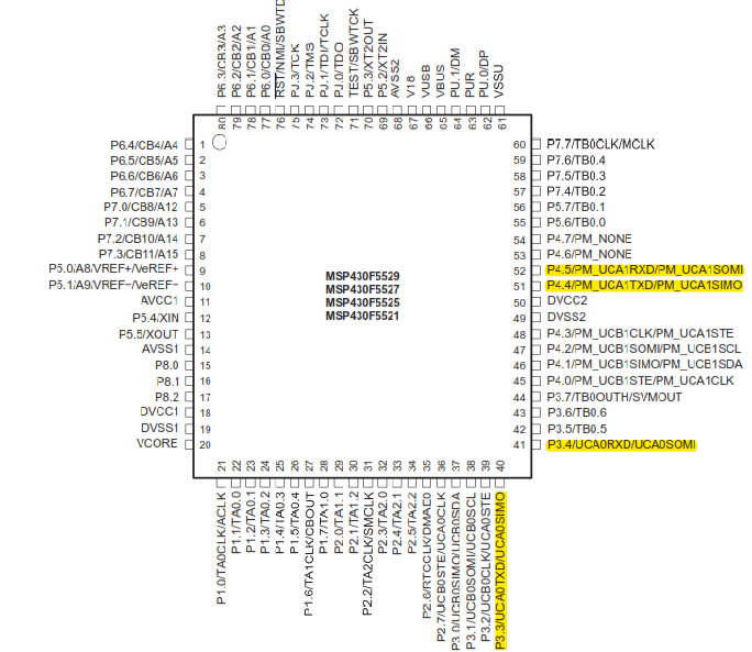
So far, I've removed  resistors R49, R53 and R60 from the 'PL536, and I have modified the software available to use P1.5 instead of P1.1 (on the MSP430 LP) for the FAULT signal from the 'PL536.

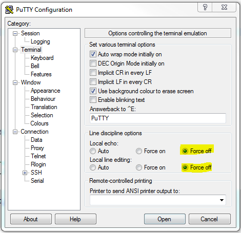
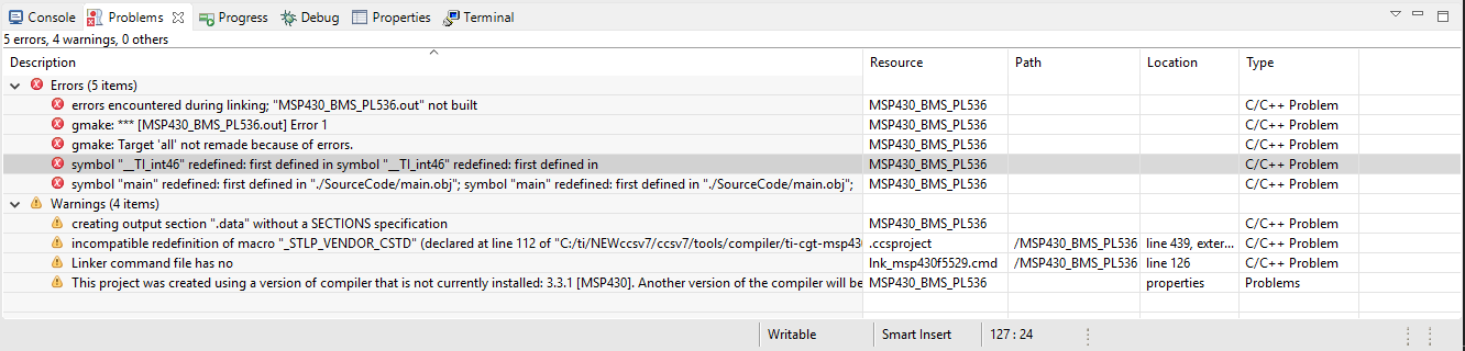
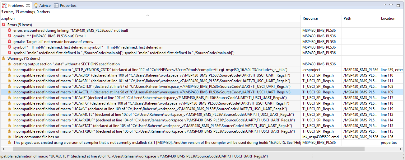
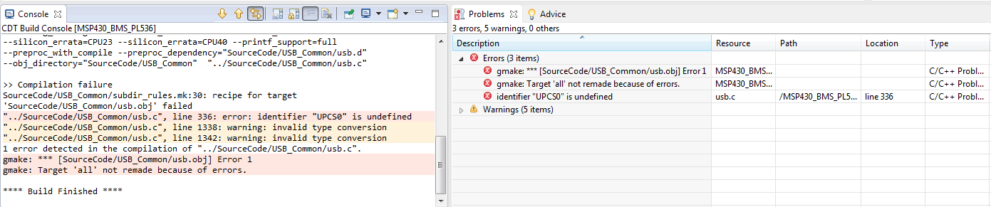
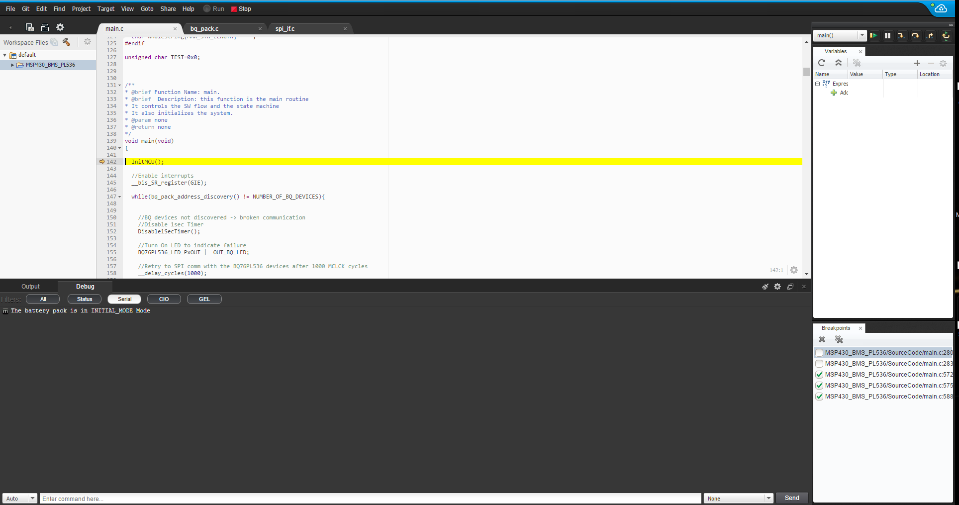
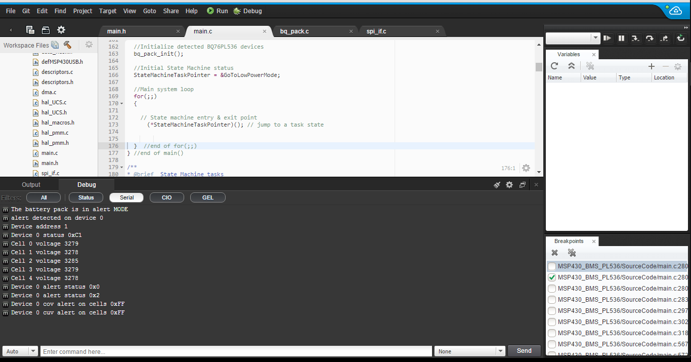
However, when everything is connected, I am not seeing any data being sent to the host PC via USB (verified using PuTTY). In fact, using CCS, I am not seeing the any of the 3 bq76PL536 devices being assigned an address in the code.

What does happen, however, is that the red LED on the MSP430 LP (P1.1) switches on and stays on (implying a connection/communication problem between the MSP and BQ). Also, some cells connectd to the 'PL536 EVM seem to be discharging through their balancing resistors, even though their voltages are lower than the other cells in the pack.

Has anyone experienced this? Does anyone have a solution?

  • Hi,

    Since you're using the MSP-EXP430F5529LP instead of the MSP-TS430PN80USB, I'd recommend carefully reading through Section 1.1 in SLAA478 to make sure all the connections are correct between the BQ76PL536EVM-3 and the MSP-EXP430F5529LP. Then, using the original unchanged provided code, try to get the example to work before modifying the code/connections. Keep in mind that the USB interfaces are different between the MSP-TS430PN80USB and MSP-EXP430F5529LP. Refer to Section 2.2.3 in the LaunchPad User's Guide for more details. In Section 2.1.3 in SLAA478, it discusses the communication ports and how the user must define it in the 'main.h' file. It appears that the USB interface has been selected by default, which is why you're not seeing anything on the UART/serial port.

    For issues related to the balancing resistors, I'd recommend posting these types of questions for the BQ76PL536 in the Battery Management - Gas Gauge Forum.

    Regards,

    James

    MSP Customer Applications

  • Hello James

    1) Yes, I have made the correct connections between the BQ76PL536EVM-3 and the MSP-EXP430F5529LP, as given in Section 1.1 of the applications. I have made all connections given in Table 1 and Table 2.

    2) I have tried using the original code, and the same thing happens. In this case, I am unable to make connections for the FAULT signal, since the code requires a connection to P1.1 on the MSP430, but this pin already has an LED connected to it on the LaunchPad. I thought re-assigning the FAULT signal to an unused pin (P1.5) would have solved the problem, but it didn't.

    3) The section of code in the 'main.h' file that Section 2.1.3 in SLAA478 refers to is the following:

    //communication protocol define
    //#define UART_COMM
    #define USB_COMM
    #define MAX_STR_LENGTH 128
    //definitions for the UART
    #ifdef UART_COMM
    #include "UART.h"
    #define MCLK_FREQ 8000000 // MCLK frequency of MCU, in Hz
    #endif
    //definitions for the USB files
    #ifdef USB_COMM
    #include "..\SourceCode\USB_Common\descriptors.h"
    #include "USB_Common\usb.h" // USB-specific functions
    #include "USBCDC_constructs.h"
    #define MCLK_FREQ USB_MCLK_FREQ // MCLK frequency of MCU, in Hz
    #ifdef _CDC_
    #include "USB_CDC_API\UsbCdc.h"
    #endif
    #endif

    The USB communcations are defined, with the UART communications being commented out.

    With a setup like this, should I not be able to use the USB A to microUSB cable to see the battery variables changing, or at least see some form of communication between the 2 devices? Or must I enable UART communications instead, then use a UART to RS232/USB cable to do this?

    Regards
  • Thanks for checking the connections. Let's try using the backchannel UART on the MSP-EXP430F5529LP, which means commenting out the USB portions and uncommenting the UART portions in the 'main.h' file. Since you're using the LaunchPad, I'd change the original UART pins shown in Table 6 in SLAA478 to be the pins mentioned in Section 2.2.6 in the LaunchPad's User's Guide. You may also have to refer to the schematic or quick user's guide for the specific pin names. Keep in mind the proper RX -> TX and TX -> RX connections.

    Let me know if this allows you to communicate with the device.

    Regards,

    James

    MSP Customer Applications

  • Hello James

    I tried your suggestion.

    Just commenting out the USB sections of code in ‘main.h’ and uncommenting the UART sections did not solve the problem. The same thing happens.

    When the program is running, suspending it consistently places the cursor within two functions: ‘spi_read_reg’ or ‘bq_pack_address_discovery’. These functions seem to be where the program is stuck/looping.

    For the second suggestion, the backchannel UART pins on the F5529 are pins P4.4 (TX) and P4.5 (RX).

    These are connected via jumpers to the ez-FET lite. Still, I made the changes from P3.3 and P3.4, to P4.4 and P4.5, respectively, in the ‘UART.h’ file. Still no change; the same thing happens. This is using the USB A to micro USB cable that came with the LaunchPad.

    Also, do these changes influence communications between the 'PL536 and LaunchPad? If I'm not mistaken, these devices use SPI to communicate, so any changes to UART should not affect the two.

    Regards

  • Thanks for trying these suggestions. After looking at 'UART.h', make sure you've changed all the UART registers to reflect the pins for the backchannel UART pins. Most importantly, the baud rate here is 57600, so you're terminal will have to match this. Also, keep in mind that you need to change the USCI_A module from "0" to "1" due to the pin changes.

    If you've already done this, let me know.

    Regards,

    James

    MSP Customer Applications
  • These are the changes I had made:

    #define USCI_A_MODULE 0 // Select which USCI_A module to use [0-1]
    #define UART_BAUDRATE 57600 //Specify baudrate
    #define UART_BAUDRATE_REG (unsigned short)(MCLK_FREQ/UART_BAUDRATE)

    //define uart registers
    #define UART_PxIN P4IN
    #define UART_PxOUT P4OUT
    #define UART_PxDIR P4DIR
    #define UART_PxIFG P4IFG
    #define UART_PxIES P4IES
    #define UART_PxIE P4IE
    #define UART_PxSEL P4SEL
    #define UART_PxREN P4REN

    #define UART_RX_PAD BIT5 // select uart pins P3.4
    #define UART_TX_PAD BIT4 // select uart pins P3.3

    I had forgotten to change the module to '1', instead of '0'. After doing so however, 'main.c' does not build.

    There is an error in the file 'TI_USCI_SPI_Regs'. I am trying to find the exact lines that caused the error.
  • Let me know if you figure out what's causing the error. There shouldn't be a conflict between the UART and SPI interfaces, but maybe I'm missing something.

    In the meantime, I modified the 'MSP430F55xx_uscia0_uart_01.c' code example to utilize the backchannel UART, so you can make sure that portion of the application works correctly. In Putty, I turned (forced) off the local echo and local line editing, updated the correct COM port to match the "MSP Application Interace" UART port, updated the baud rate to 115200, and saved the profile in Putty as "MSP430F5529" for easier loading in the future.

    In the code below, I commented out Line 107 to demonstrate that a unique value was indeed coming from the MSP430. In this configuration, after programming the board and stopping debug, and opening your saved session in Putty, you can type anything, and the MSP430 will send back "h", since this is hard-coded in Line 108 as "0x68" in hexadecimal. If you uncomment Line 107 and comment out Line 108, then whatever you type in the Putty terminal will be sent back from the MSP430. Also, LED1 will blink dimly (since it happens so quickly) on the LaunchPad, signifying that the UART ISR has been executed.

    /* --COPYRIGHT--,BSD_EX
     * Copyright (c) 2012, Texas Instruments Incorporated
     * All rights reserved.
     *
     * Redistribution and use in source and binary forms, with or without
     * modification, are permitted provided that the following conditions
     * are met:
     *
     * *  Redistributions of source code must retain the above copyright
     *    notice, this list of conditions and the following disclaimer.
     *
     * *  Redistributions in binary form must reproduce the above copyright
     *    notice, this list of conditions and the following disclaimer in the
     *    documentation and/or other materials provided with the distribution.
     *
     * *  Neither the name of Texas Instruments Incorporated nor the names of
     *    its contributors may be used to endorse or promote products derived
     *    from this software without specific prior written permission.
     *
     * THIS SOFTWARE IS PROVIDED BY THE COPYRIGHT HOLDERS AND CONTRIBUTORS "AS IS"
     * AND ANY EXPRESS OR IMPLIED WARRANTIES, INCLUDING, BUT NOT LIMITED TO,
     * THE IMPLIED WARRANTIES OF MERCHANTABILITY AND FITNESS FOR A PARTICULAR
     * PURPOSE ARE DISCLAIMED. IN NO EVENT SHALL THE COPYRIGHT OWNER OR
     * CONTRIBUTORS BE LIABLE FOR ANY DIRECT, INDIRECT, INCIDENTAL, SPECIAL,
     * EXEMPLARY, OR CONSEQUENTIAL DAMAGES (INCLUDING, BUT NOT LIMITED TO,
     * PROCUREMENT OF SUBSTITUTE GOODS OR SERVICES; LOSS OF USE, DATA, OR PROFITS;
     * OR BUSINESS INTERRUPTION) HOWEVER CAUSED AND ON ANY THEORY OF LIABILITY,
     * WHETHER IN CONTRACT, STRICT LIABILITY, OR TORT (INCLUDING NEGLIGENCE OR
     * OTHERWISE) ARISING IN ANY WAY OUT OF THE USE OF THIS SOFTWARE,
     * EVEN IF ADVISED OF THE POSSIBILITY OF SUCH DAMAGE.
     *
     *******************************************************************************
     * 
     *                       MSP430 CODE EXAMPLE DISCLAIMER
     *
     * MSP430 code examples are self-contained low-level programs that typically
     * demonstrate a single peripheral function or device feature in a highly
     * concise manner. For this the code may rely on the device's power-on default
     * register values and settings such as the clock configuration and care must
     * be taken when combining code from several examples to avoid potential side
     * effects. Also see www.ti.com/grace for a GUI- and www.ti.com/msp430ware
     * for an API functional library-approach to peripheral configuration.
     *
     * --/COPYRIGHT--*/
    //******************************************************************************
    //   MSP430F552x Demo - USCI_A1, 115200 UART Echo ISR, DCO SMCLK
    //
    //   Description: Echo a received character, RX ISR used. Normal mode is LPM0.
    //   USCI_A1 RX interrupt triggers TX Echo.
    //   Baud rate divider with 1048576hz = 1048576/115200 = ~9.1 (009h|01h)
    //   ACLK = REFO = ~32768Hz, MCLK = SMCLK = default DCO = 32 x ACLK = 1048576Hz
    //   See User Guide for baud rate divider table
    //
    //                 MSP430F552x
    //             -----------------
    //         /|\|                 |
    //          | |                 |
    //          --|RST              |
    //            |                 |
    //            |     P4.4/UCA1TXD|------------>
    //            |                 | 115200 - 8N1
    //            |     P4.5/UCA1RXD|<------------
    //
    //   Bhargavi Nisarga
    //   Texas Instruments Inc.
    //   April 2009
    //   Built with CCSv4 and IAR Embedded Workbench Version: 4.21
    //******************************************************************************
    
    #include <msp430.h>
    
    int main(void)
    {
      WDTCTL = WDTPW + WDTHOLD;                 // Stop WDT
    
      P1DIR |= BIT0;	                        // P1.0 = LED1
      P1OUT &= ~BIT0;							// Turn LED1 off
      P4SEL |= BIT4+BIT5;                       // P4.4,5 = USCI_A1 TXD/RXD
      UCA1CTL1 |= UCSWRST;                      // **Put state machine in reset**
      UCA1CTL1 |= UCSSEL_2;                     // SMCLK
      UCA1BR0 = 9;                              // 1MHz 115200 (see User's Guide)
      UCA1BR1 = 0;                              // 1MHz 115200
      UCA1MCTL |= UCBRS_1 + UCBRF_0;            // Modulation UCBRSx=1, UCBRFx=0
      UCA1CTL1 &= ~UCSWRST;                     // **Initialize USCI state machine**
      UCA1IE |= UCRXIE;                         // Enable USCI_A1 RX interrupt
    
      __bis_SR_register(LPM0_bits + GIE);       // Enter LPM0, interrupts enabled
      __no_operation();                         // For debugger
    }
    
    // Echo back RXed character, confirm TX buffer is ready first
    #if defined(__TI_COMPILER_VERSION__) || defined(__IAR_SYSTEMS_ICC__)
    #pragma vector=USCI_A1_VECTOR
    __interrupt void USCI_A1_ISR(void)
    #elif defined(__GNUC__)
    void __attribute__ ((interrupt(USCI_A1_VECTOR))) USCI_A1_ISR (void)
    #else
    #error Compiler not supported!
    #endif
    {
      switch(__even_in_range(UCA1IV,4))
      {
      case 0:break;                             // Vector 0 - no interrupt
      case 2:                                   // Vector 2 - RXIFG
    	P1OUT = BIT0;							// Turn LED1 on
        while (!(UCA1IFG&UCTXIFG));             // USCI_A1 TX buffer ready?
        //UCA1TXBUF = UCA1RXBUF;                  // TX -> RXed character
        UCA1TXBUF = 0x68;                  // TX -> RXed character
        P1OUT &= ~BIT0;							// Turn LED1 off
        break;
      case 4:break;                             // Vector 4 - TXIFG
      default: break;
      }
    }
    

    Regards,

    James

    MSP Customer Applications

  • Hello James,

    I tried implementing this code, but it did not build. The errors were caused by the following lines:

    UCA1CTL1 |= UCSWRST; // **Put state machine in reset**
    UCA1CTL1 |= UCSSEL_2; // SMCLK
    UCA1BR0 = 9; // 1MHz 115200 (see User's Guide)
    UCA1BR1 = 0; // 1MHz 115200
    UCA1MCTL |= UCBRS_1 + UCBRF_0; // Modulation UCBRSx=1, UCBRFx=0
    UCA1CTL1 &= ~UCSWRST; // **Initialize USCI state machine**
    UCA1IE |= UCRXIE; // Enable USCI_A1 RX interrupt

    Apparently, those variables are not defined. Shouldn't those be in the msp430.h header file?

    Regards
  • This is what appears when I try to build the original program ('main.c'):

    The first time when I tried building the program, and it failed, the file 'TI_USCI_SPI_Regs.h' has the mini yellow triangle next to it. Whenever I try building again to look for the errors, that triangle does not appear anymore.

    EDIT:

    Restarted the program, and the warnings appeared again:

  • Hi Raheem,

    What version of CCS are you using? I'm asssuming (and also using) CCS v7. I downloaded the code and tried to build it, but I encountered an error pointing to 'usb.c'. Keep in mind I didn't make any changes to any other files. After removing "UPCS0 + " from Line 336, the code built without any errors. I found this solution in this thread.

    Next, I'll try to make the same changes as you to see if I can duplicate your errors.

    Regards,

    James

    MSP Customer Applications

  • After the change above, next I changed the #define from "USB_COMM" to "UART_COMM" in 'main.h' as shown below.

    //communication protocol define
    #define UART_COMM
    //#define USB_COMM
    #define MAX_STR_LENGTH 128
    //definitions for the UART  
    #ifdef UART_COMM
      #include "UART.h"
    #define MCLK_FREQ 8000000 // MCLK frequency of MCU, in Hz
    #endif
    //definitions for the USB files
    #ifdef USB_COMM
    #include "..\SourceCode\USB_Common\descriptors.h"
    #include "USB_Common\usb.h"        // USB-specific functions
    #include "USBCDC_constructs.h"
    #define MCLK_FREQ USB_MCLK_FREQ   // MCLK frequency of MCU, in Hz
      #ifdef _CDC_
        #include "USB_CDC_API\UsbCdc.h"
      #endif
    #endif

    Next, I changed 'UART.h' to utilize the backchannel UART pins, P4.4 and P4.5 as shown below.

    #ifndef UART_H_
    #define UART_H_
    
    #define USCI_A_MODULE  1     // Select which USCI_A module to use [0-1]
    #define UART_BAUDRATE  57600 //Specify baudrate
    #define UART_BAUDRATE_REG  (unsigned short)(MCLK_FREQ/UART_BAUDRATE)
    
    //define uart registers
    #define UART_PxIN      P4IN
    #define UART_PxOUT     P4OUT
    #define UART_PxDIR     P4DIR
    #define UART_PxIFG     P4IFG
    #define UART_PxIES     P4IES
    #define UART_PxIE      P4IE
    #define UART_PxSEL     P4SEL
    #define UART_PxREN     P4REN
    
    #define UART_RX_PAD    BIT5 // select uart pins P4.5
    #define UART_TX_PAD    BIT4 // select uart pins P4.4
    
    
    #include "TI_USCI_UART_Regs.h"
    //Global Functions
    extern void InitUART(void);
    extern void StartUARTRx(void);
    extern void StopUARTRx(void);
    extern void WriteUART(unsigned char data);
    extern void putsUART(unsigned char *buffer, unsigned short StringSize);
    
    
    #endif /*UART_H_*/

    I didn't encounter any errors after rebuilding. Perhaps you commented out too many lines of code in 'main.h'?

    Regards,

    James

    MSP Customer Applications

  • Hello James

    I am using CCS v7. I could not find the source of the errors, and I had the same lines commented out in ‘main.h’ as you do.

    What I did instead, was remove all projects from the workspace, then re-installed CCS v7. This seems to have fixed the problem – there are no errors now when ‘main.c’ is built.

    I tried using the 'MSP430F55xx_uscia0_uart_01.c' code example, and this worked fine now, with no errors.

    I do not have the LaunchPad connected to the ‘PL536 at the moment, but looking at the terminal through PuTTY, I am still not seeing anything being received/transmitted. Should there not be an output string from the LaunchPad saying that no ‘PL536 devices were found?

    Additionally, I recently learned that IC2 on the ‘PL536EVM is dead, which prevents me from using both IC2 and IC3. This means that effectively, the LaunchPad can only address IC1. Thus, I made the following changes to the ‘data_flash.h’ file:

    //Battery pack definition
    #define NUMBER_OF_BQ_DEVICES      1  //3 BQ76PL536 devices are connected
    #define NUMBER_OF_CELLS           6 //MAX number of cells in the system
    #define MAX_CELLS_NUMBER_IN_BQ    6  //MAX number of cells per BQ76PL536 device
    #define CELL_BALANCING_EN         1  //set to 1 to enable cell balancing
    #define ONE_MINUTE                     60

    Regards

  • Hi Raheem,

    Good job resolving those build errors! Maybe another project/workspace was affecting it somehow. In CCS, I generally keep a separate workspace for each project, and also when I import a project into CCS, I make sure to check the "Copy projects into workspace" option before finishing the import process. This way, it copies the original project into the workspace, so if necessary, you can delete the workspace without deleting the original project.

    Now, after programming the LaunchPad with the code changed to UART communication, LED1 (P1.0) is ON. However, after looking through SLAA478 to see what this means, I noticed that the signals/pins in Figure 1 do NOT match those listed in Table 1. Looking at the #defines in the 'bq_pack.h' file, the signals in the code match the pin descriptions in Table 1. I'll submit feedback to get Figure 1 updated accordingly.

    Back to P1.0, this is defined as the "OUT_BQ_LED" in 'bq_pack.h'. In 'main.c', I put a breakpoint at Line 155. In this while() loop, LED1 (P1.0) is turned on if the BQ devices are not discovered, which makes sense because I don't have the BQ EVM or have it connected. Thus, the code never gets to the point where it can send information to the terminal.

    Regards,

    James

    MSP Customer Applications

  • I'm concerned that there may be other issues with the BQ76PL536EVM-3 if IC2 and IC3 are dead. Ideally, this wouldn't affect anything but it definitely could.

    On the LaunchPad, I went back to USB CDC instead of UART. After programming the LaunchPad, I went to Device Manager and under "Other devices", the MSP430 CDC was shown, but the driver wasn't installed correctly. Following the instructions in Section 2.1.3.1 in SLAA478, I proceeded to install the 'MSP430_CDC.inf' driver found in the SLAA478 folder. The instructions mention the proper procedure to connect the device to the host PC and then open a terminal for the Virtual CDC COM port (according to instructions, the baud rate doesn't matter). Try this with the BQ76PL536EVM-3 connected to the LaunchPad programmed with your changes in your 'data_flash.h' file. Your configuration for a single BQ device looks OK, but there could be damage to other devices on the BQ76PL536EVM-3.

    Let me know if you can get past the while() loop in 'main.c' that checks the BQ devices and moves past keeping LED1 ON.

    Regards,

    James

    MSP Customer Applications
  • Hello James

    I spent the day speaking with the supplier for the bq76PL536EVM-3, and discovered that the device is a returned device. Hence, it is very likely that there may be other issues with the EVM. Considering that IC1 still works, I want to believe that if the communications area on the EVM was still functional, the MSP would be able to read data from the EVM, over SPI, but I am not sure. I will post in the Battery Management part of the forum to see if there is a way to test the communications interface on the bq76PL536EVM-3. I am doing this to stay occupied while I await the replacement part.

    Regarding the LaunchPad, I have never been prompted for a driver. I tried installing 'MSP430_CDC.inf', but received the error 'The third-part INF does not contain digital signature information'. I am attempting to resolve this now.

    I will update you further when I step through the code in 'main.c', to see if I can get past that while() loop.

    Regards

  • Hi Raheem,

    It sounds like you're making good progress. Regarding the driver, I didn't see the device popup in the bottom right when I had configured it for the UART communication, but after programming it for the USB communication, I halted debug and disconnected/reconnected the LaunchPad to my PC. A popup appeared on the bottom right, saying that the driver had not been installed. After going to Device Manager and finding the Virtual COM, I manually pointed the driver to the SLAA478 folder where the 'MSP430_CDC.inf' is located. I too got a warning about using the driver, but I just accepted that and completed the installation. Hopefully this helps clarify what I did.

    Let me know if anything is unclear.

    Regards,

    James

    MSP Customer Applications

  • Hello James

    By switching back to USB CDC from UART, I assumed you meant enabling USB comms in 'main.h', and reverting back to previous UART settings in 'UART.h'. This is what I did. Next, I disconnected and reconnected the LaunchPad, but there was no pop-up asking for a driver. However, in Device Manager, this is what I am seeing:

    I assume that the presence of USB Serial Device (COM5) under Ports means that the driver is already installed. I have never been prompted for it, however, so perhaps it may have been automatically installed?

    Regarding the while() loop in 'main.c', I am unable to get past that loop. LED1 turns on, and the delay occurs, then the cycle repeats itself. I believe this may be sufficient indication that there is damage to the isolated communications interface on the EVM.

    Regards

  • Raheem Hall said:
    By switching back to USB CDC from UART, I assumed you meant enabling USB comms in 'main.h', and reverting back to previous UART settings in 'UART.h'. This is what I did.

    Correct. I didn't change anything in 'UART.h', since changing the #define in 'main.h' to "USB_COMM" uses 'usb.h' instead.

    Raheem Hall said:
    Next, I disconnected and reconnected the LaunchPad, but there was no pop-up asking for a driver. However, in Device Manager, this is what I am seeing:

    This is strange. Perhaps it's because I'm using Windows 7 and you're using Windows 8 or 10. When I changed back to USB_COMM and connected the LaunchPad, that's when the pop-up was displayed. After going to Device Manager, I found the USB CDC under "Other devices". Clicking on it and re-configuring the driver, the LaunchPad now shows up as Virtual COM port in Device Manager now. If you've configured your code for USB_COMM and reprogrammed the board and you're still seeing it as USB Serial Device (COM5), I'd try manually re-configuring that driver with the 'MSP430_CDC.inf' file.

    Raheem Hall said:
    Regarding the while() loop in 'main.c', I am unable to get past that loop. LED1 turns on, and the delay occurs, then the cycle repeats itself. I believe this may be sufficient indication that there is damage to the isolated communications interface on the EVM.

    If you aren't able to get past the while() loop, it doesn't seem like the single device can be found over SPI, which is strange if the boards are connected properly. However, if the board is damaged, this would make sense. Hopefully you can obtain a working BQ EVM.

    Regards,

    James

    MSP Customer Applications

  • As a side note, are you powering the BQ76PL536EVM-3 with 3.3V or 5V? Perhaps, the EVM is operating at 5V I/O, and this is why the ICx and/or SPI interface isn't working. Can you make sure JP5 is set for 3.3V operation according to Section 3.1.1 in bq76PL536A and bq76PL536A-Q1 EVM Quick Start Guide? 5V I/O's would affect the MSP430 if voltage translators aren't used.

    Regards,

    James

    MSP Customer Applications

  • Hello James

    I tried disconnecting and reconnecting again, but the USB Serial Device (COM5) still shows up. I am not seeing an 'Other Devices' section, nor a Virtual COM Port. I tried updating the driver for the USB Serial Device, and Windows says 'the best software for my device is already installed'. I am using Windows 10.

    As for powering the bq76PL536EVM-3, there are 20 jumpers on the board. JP1 to JP18 are jumpers to connect the cells to 1k precision resistors; only JP19 and JP20 are on the isolated communications interface area.

    As I received the board, JP20 is configured to connect the EXT-5VDC and USB pins. JP19 is connecting the 5.0V and 3.3V pins.

    From what I understand in Section 3.1.1 in bq76PL536A and bq76PL536A-Q1 EVM Quick Start Guide, JP20 needs to connect the USB pin to the 3rd pin, and JP19 should connect the 3.3V pin to the 3rd pin. Is this correct?

    Finally, does the source of the 5V supply for SPI from the LaunchPad matter? I am using the 5V and GND from J3, rather than those from the 40-pin BoosterPack area.

    Regards

  • Hello James

    I tried the configuration I explained in my previous post, and LED1 is now blinking steadily. I am planning to switch back to UART to see if anything is happening at the terminal. Will post an update when I have results.

    Regards

  • Hello James

    Using UART Communications, there was activity at the COM Port, verified using PuTTY. The only message that was sent from the MSP430 to the host PC was "The battery pack is in INITIAL_MODE Mode."

    Next, I decided to attempt create a GUI using GUI Composer V2 on the cloud, since I am using CCS v7. I uploaded the project to my CCS Cloud, then programmed the MSP430 from there. This time, after connecting to the COM port via CCS Cloud, I saw actual cell voltage data being sent to the host PC. But then, the system entered ALERT mode, and LED1 on the LaunchPad remained on. I ran the program again, and the same thing happened, except some cell voltage data were irregular, reading over 25V. I ran the program again, and then it put me pack to square one; the only message being transmitted was again, "The battery pack is in INITIAL_MODE Mode" :

    I stepped through the program to see what really happens. I found that it never gets to the UARTCommunicationTask() function (line 567 in 'main.c'). All that happens is it gets to the Timer1SecExpiredTask() function (line 277 in 'main.c'), and inside that function, there is another function, bq_pack_start_conv(). This function takes the program to 'spi_if.c' to a function spi_write_reg(), which runs 4 times. The program then returns to 'main.c', at the end of the main() function.

    Since UART communications were not working, I decided to revert back to USB communications. CCS Cloud was unable to open the terminal to the COM Port for the USB Serial Device, so I could not see if anything was actually being transmitted. Nevertheless, I stepped through the code to see what was happening.

    When the program got to the USBCommunicationTask() function (line 701 in 'main.c'), it entered the case ST_ENUM_ACTIVE in the switch case, then proceeded to the default action, which is nothing. The program then returned to the low power mode to await the next interrupt from the 1 second timer.

    Do you have any idea what may be causing these issues? I am still using the damaged EVM while I await delivery of the new EVM - is this likely to be the reason?

    EDIT:


    As I finished typing that, there was an update in the terminal. This is what I can see now:

    LED1 is still blinking though, implying that there is still communication, and the pack is not actually in alert mode. That update above has been the only one in about 15 minutes.

    Regards

**Attention** This is a public forum