This thread has been locked.

If you have a related question, please click the "Ask a related question" button in the top right corner. The newly created question will be automatically linked to this question.

Connecting BQ76PL536EVM with MSP-EX430F5529LP using sample code

Other Parts Discussed in Thread: BQ76PL536, BQ76PL536EVM-3, MSP-TS430PN80USB

Dear Forum, 

In trying to make my BQ76PL536EVM talk to a microcontroller, I found the TI application report - SLAA478 - "Multi-cell Li-Ion BMS using MSP430F5529 and bq76PL536", which describes the connections and a code sample to be run on the micro-controller for communication. 

Now, I ordered the MSP-430 Launchpad (MSP-EX430F5529LP), with the same microcontroller. Will this board work with bq76PL536A ?

To try on my own, I built the provided code in CCS, and uploaded it to the device. I have not been able to figure out what to do next. I opened 'putty' (hyperterminal alternative) and observed all the available COM ports, but found no communication. I also tried the same from within CCS and still no results. (i am expecting that the sample should print battery status)

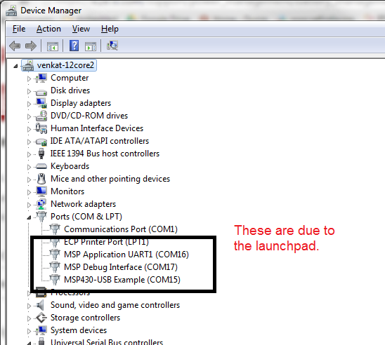
The launchpad is working fine as I ran the "blink" example and it worked. I also installed MSP ware and USB drivers, so the launchpad populates three COM ports as shown in the attached image.

The battery monitor is working fine, as I tested it with Aardvark adapter and then use a power supply (in place of batteries) to connect across Pins 1 and 7 of the first chip only. 

Any directions related to the issue are greatly appreciated. 

Thanks 

Chintan Pathak 

Research Scholar,

University of Washington

  • Hello Chintan,

    The BQ76PL536EVM-3 should be able to work with the MSP-EX430F5529LP given that all of the connections in Table 1 of the mentioned application report (SLAA478) are correct. How are you connecting P1.1, since it is not available on a LaunchPad pin? Have you ensured that the eZ-FET lite jumpers are populated and oriented correctly? Have you followed all instructions provided in Sections 1 & 2 of the application report?

    Regards,
    Ryan
  • Hi Chintan,

    On the launch pad make sure that:

    1. USCI_B0 as the SPI port
    2. If P1.1 thru P1.4 are not available, you will need to select 4 pins available on the booster pack connector and then modify the SW accordingly.

    You need all this pins to control the state of the BQ75PL536.

    Regards,

    Daniel

  • @Ryan: 

    Thanks for your response. I have made all the connections as required in Table - 1. I have only connected pin 6 of P5 header on BQ76 to 5V, and not Pin 4, similarly I have only connected pin 2 of P5 to GND and not pin 10. The attached schematic of BQ76, pg 1, shows the detail of the P5 header. 

    Other than this, I have made all the connections except, P4, pin2, "Fault" to be connected to P1.1 of MSP430. I had read somewhere, that the P4 connections are all optional and the basic voltage, temperature reporting from BQ76 should work even without those connections. If this is not so, and if P1.1 is required, then should I try connecting it by soldering to the underside of switch S2 ?

    As for the Jumper connections on eZ-FET lite, I have left them unchanged from the factory settings, which means everything except RTS and CTS is populated. I read the EVM user manual but am not certain. Do I need jumpers on RTS and CTS ? Do I need to remove any other jumpers ? I dont get what you mean by jumper orientation.

    I think the section 2 of App report details about the software part, and I have not made any changes to it. So I was hoping it would work out of the box. I have tried to follow with settings in Section 1. I have also tried making the change in "main.h" which selects between USB and UART as described in 2.1.3 of App report, but that hasnt helped. 

    @ Daniel: 

    Thank you for your response. I have connected the SPI pins as under. 

    SPI: Select Slave                                    P5-9 : SPI SS/GPIO                     J2-36 : P2.7/USCB0STE
    SPI: Slave Input/Master Output              P5-8 : SPI MOSI/GPIO                J2-37 : P3.0/USCB0SIMO
    SPI: Slave Output/Master Input              P5-5 : MISO/GPIO                       J2-38 : P3.1/USCB0SOMI
    SPI: Clock                                               P5-7 : SCLK/GPIO                       J2-39 : P3.2/USCB0CLK

    although I do not understand what you mean by USCI_B0 as the SPI Port, Do I need to make any changes to the code to implement this? I could not find anything relevant in the datasheet to make it SPI specific.

    Also, I was able to connect P1.2 - P1.4 to the respective pins on BQ76 as shown in the App report. If P1.1 is compulsively needed, then is there a software only solution that would allow me to connect P4.2 of BQ76 to some pin, other than P1.1  of MSP430 and make the code still work ? Can you hint what those code changes would be ?

    Thanks 

    Chintan Pathak bq76PL536EVM-3 schematics and layout.pdf

  • Chintan,

    Yes, you are using/connecting the correct serial port the USCB. This is what I was eluding to in my previous reply. You do not make changes to the SW as long as you use the exact connections. This includes P1.1. again you can use a different pin but you will have to update the SW accordingly.

    Check the bq_pack.h file line 134. You can assign anther pin on P1 by changing the bit number from 1 to the desired bit.

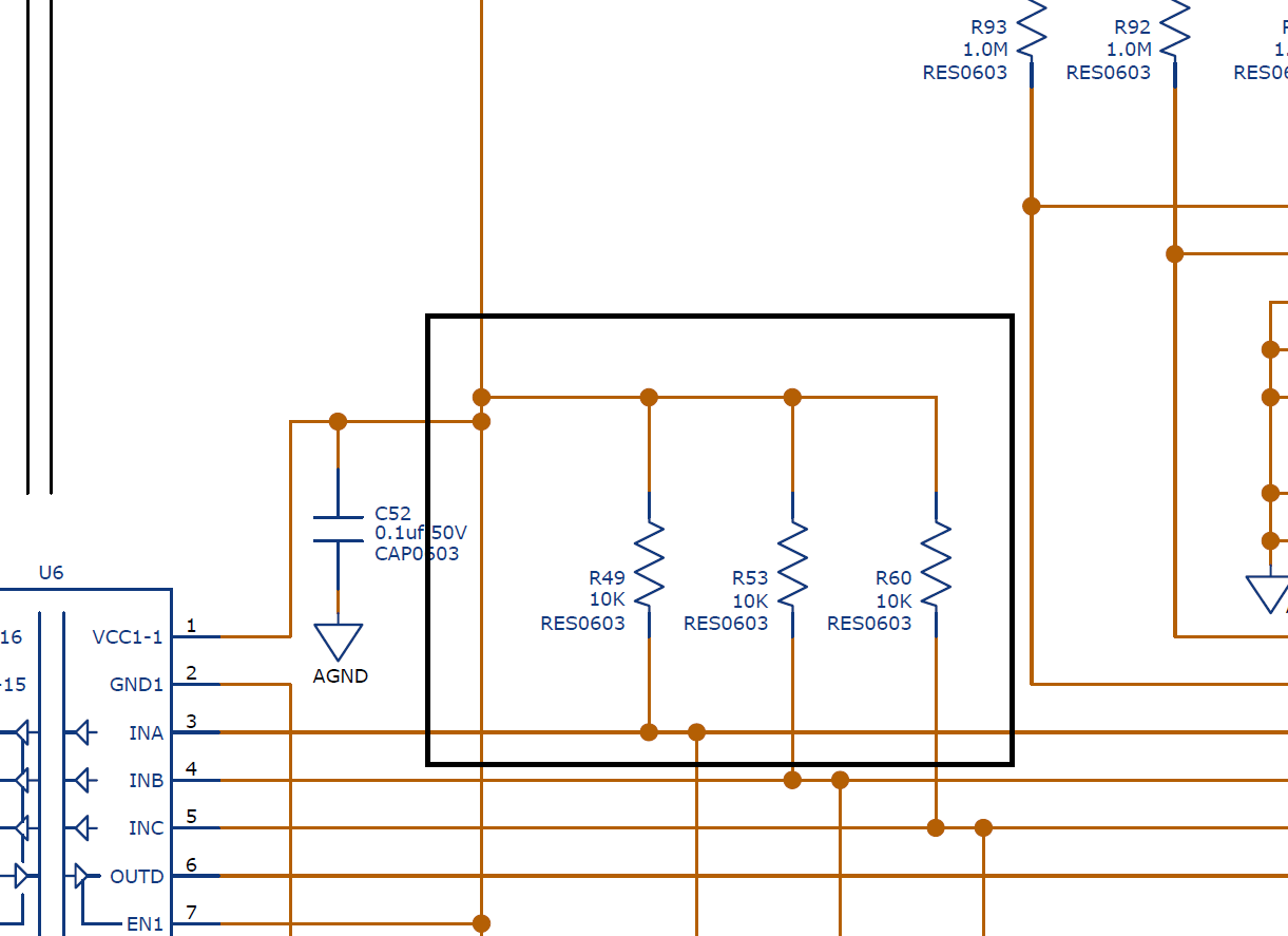
    Make sure the PL536 EVM is properly configured. Pull-up resistors R49, R53, and R60 are removed on the
    BQ76PL536EVM-3 board and the jumpers are set in the right position, follow the connections described on tables 2-5. They are very important, you could damage your EVMs if you do not follow these connections.

    Regards,
    Daniel
  • @Daniel:

    Thanks, that last observation is a good catch. Had glossed over that note in the app report. I now have the MSP-TS430PN80USB, setup exactly as in the app report.

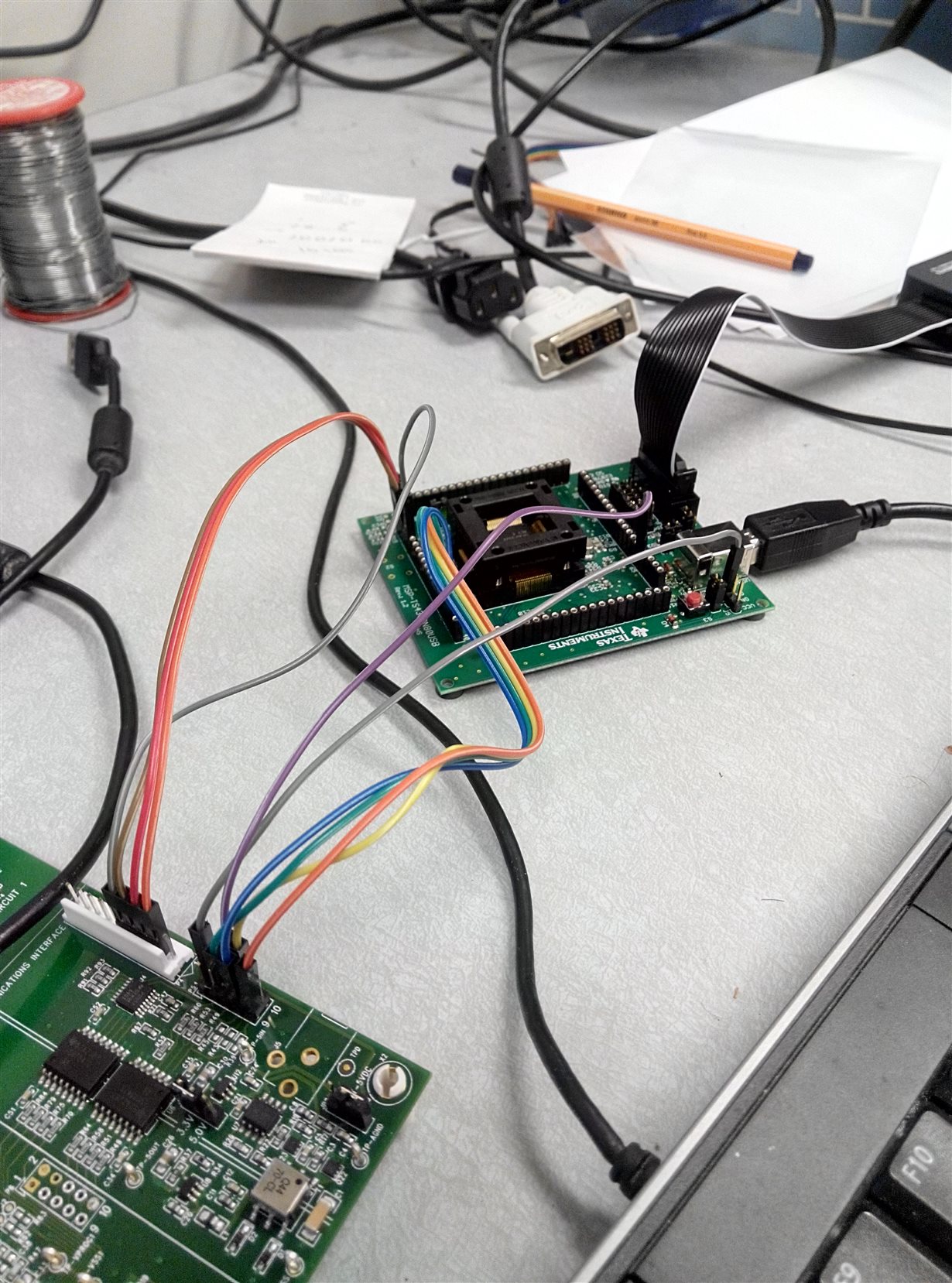
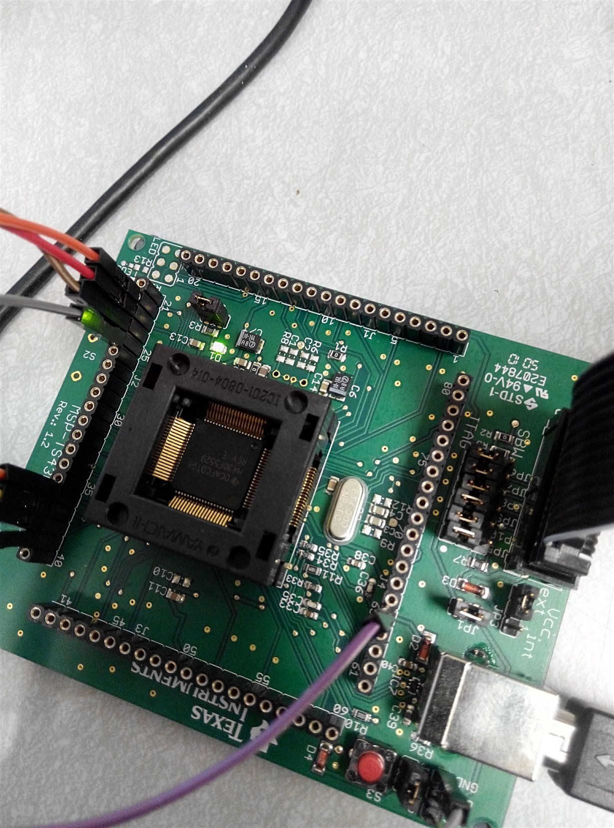
    I am attaching images of my current setup, and while the CCS project builds and uploads to the uC using the JTAG 14-pin connector, I am not observing any output on PuTTY. 

    I have a doubt regarding the JP3 on MSP430 board. As per table 3 of App report, JP3 should be between 2-3, which would be EXT, and this setting is same for external power supply (Table-5). So even if I want to power my MSP board through USB1 connector and not through an external charger, I would JP3 between 2-3. Although I have tried both I want to know if this is a typo in the app-report. 

    Finally, about R49, R53, and R60. Why do they need to be removed and how to do that on the EVM ?

    Thanks 

  • Chintan,

    JP3 has to be on position 2-3 (external) to avoid conflicts with the power provided by the JTAG debugger (it has a diode to OR-ing). The internal silkscreen on the board means that you are powering the device/board using the JTAG. Check the MSP430 Hardware Tools User's Guide (Rev. X) page 116.

    Don't remove any resistor just yet. I am double checking the resistor values. Can you let me know what rev of the PL536 EVM you have?

    Also, make sure that you have the MSP430 USB CDC driver installed. To verify this, run the code examples available in the USB developers pack. USB drivers should be there as well.

    http://software-dl.ti.com/msp430/msp430_public_sw/mcu/msp430/MSP430_USB_Developers_Package/latest/index_FDS.html

    Regards,

    Daniel


  • @ Daniel: 

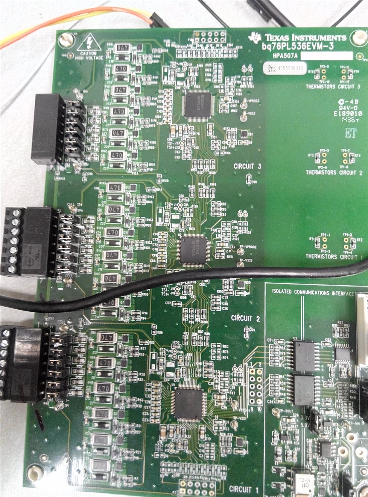
    Thank you for your continuous support, and sorry for the late reply. I am attaching the image of BQ76PL536EVM-3 (HPA507A). There are also other numbers if you want to see on the image, its probably the latest version and I bought it roughly a month ago directly from TI. I also found the schematics which I had attached previously, which do not show the resistors R49, R53 and R60. 

    I am waiting for your final call on whether to remove the resistors or not, and will report the results of running a few USB examples. 

    Thanks 

  • @ Daniel : I was also able to verify the USB drivers and that the examples in USB_API - SimpleSend and LEDOnOff do work on MSP430. I had to however, change jumper JP3 to 1-2 when uploading the program, and then back to 2-3 when trying to read the serial port. Besides, sometimes it required a few terminal restarts and USB reconnection for it to work. But that issue has already been mentioned in few places.
  • Found the pull-ups in the schematic, page number 5, they are all 10K, attaching image.  Should I remove them or leave them on ?

    Thanks

  • @ Daniel: Sorry I lacked patience. I just removed the pull-ups. And tried again. To no avail.

    To shed more light on the exact situation, I want to compare this with the LEDOnOff example in the USB_API. It asks us to open a serial connection (virtual COM) to the device and then pass commands "LED ON" to switch on and "LED OFF" to switch the LED off. And after a restart, if not directly the terminal ends up accepting input and then acting on it. However, with the BQ76 code the terminal displays no output when I type, not even the typed alphabets. Any idea why this could be happening ?
  • Chintan,

    You will have to bear with me for a few days as I am trying to connect the find the boards we used for putting together this app note. I want to make sure I can have a setup I can use to replicate the challenges you seem to have with your system.

    My best guess (without having HW available on my desk now) is that the communication between the two boards is hanging up. I need to go back an put my system together to make sure this is the case. For this reason I need you to bear with me and give me a few days.
    Daniel
  • @Daniel: Upon restarting fresh, I verified that all the connections are made correctly. All the jumper configs etc are in place. I started with the fresh code from TI website. and I try to build it. And I am thrown an error, something I had gotten last time too, which I had resolved. 

    The error is in file usb.c : Line 336  

    Description                                  Resource  Path                                                                           Location  Type      identifier

    "UPCS0" is undefined                  usb.c   /MSP430_BMS_PL536/SourceCode/USB_Common line 336 C/C++    Problem

    I had read some previous occurrences of this error, like here  

    and ended up removing the reference to UPSC0 altogether. So the code I was using previously was: 

    if (USB_PLL_XT == 2)
        {
            USBPLLCTL =  UPFDEN + UPLLEN;// Select XT2 as Ref / Select PLL for USB / Discrim. on, enable PLL // Removed as patch + UPCS0
        }																									// e2e.ti.com/.../268483
        else
        {
            USBPLLCTL = UPFDEN + UPLLEN;        // Select XT1 as Ref / Select PLL for USB / Discrim. on, enable PLL
        }

    Is this the correct way to patch this error ? Or could this be a reason for no communication over USB. 

    Thanks 

    Chintan Pathak 

  • Hello Chintan,

    This is the recommended setting for USBPLLCTL as the UCLKSEL bits should be zero (for default PLLCLK select) and all other bits besides UPFDEN and UPLLEN are reserved. As it stands, this is the correct fix for this error and is not the reason for failed USB communication.

    Regards,
    Ryan
  • @ Daniel: Were you able to reproduce the error ?

    Any other ideas on debugging the system ?

    Thanks

**Attention** This is a public forum