This thread has been locked.
If you have a related question, please click the "Ask a related question" button in the top right corner. The newly created question will be automatically linked to this question.
In my code I have enabled ALL of the USCI_B module's interrupts, set the GIE bit and have an ISR with the correct interrupt vector. (used the vector and ISR name from TI's example code) Currently I use polling to implement I2C. However I'd like to do it the proper way using interrupts to save power since this will a battery operated device.
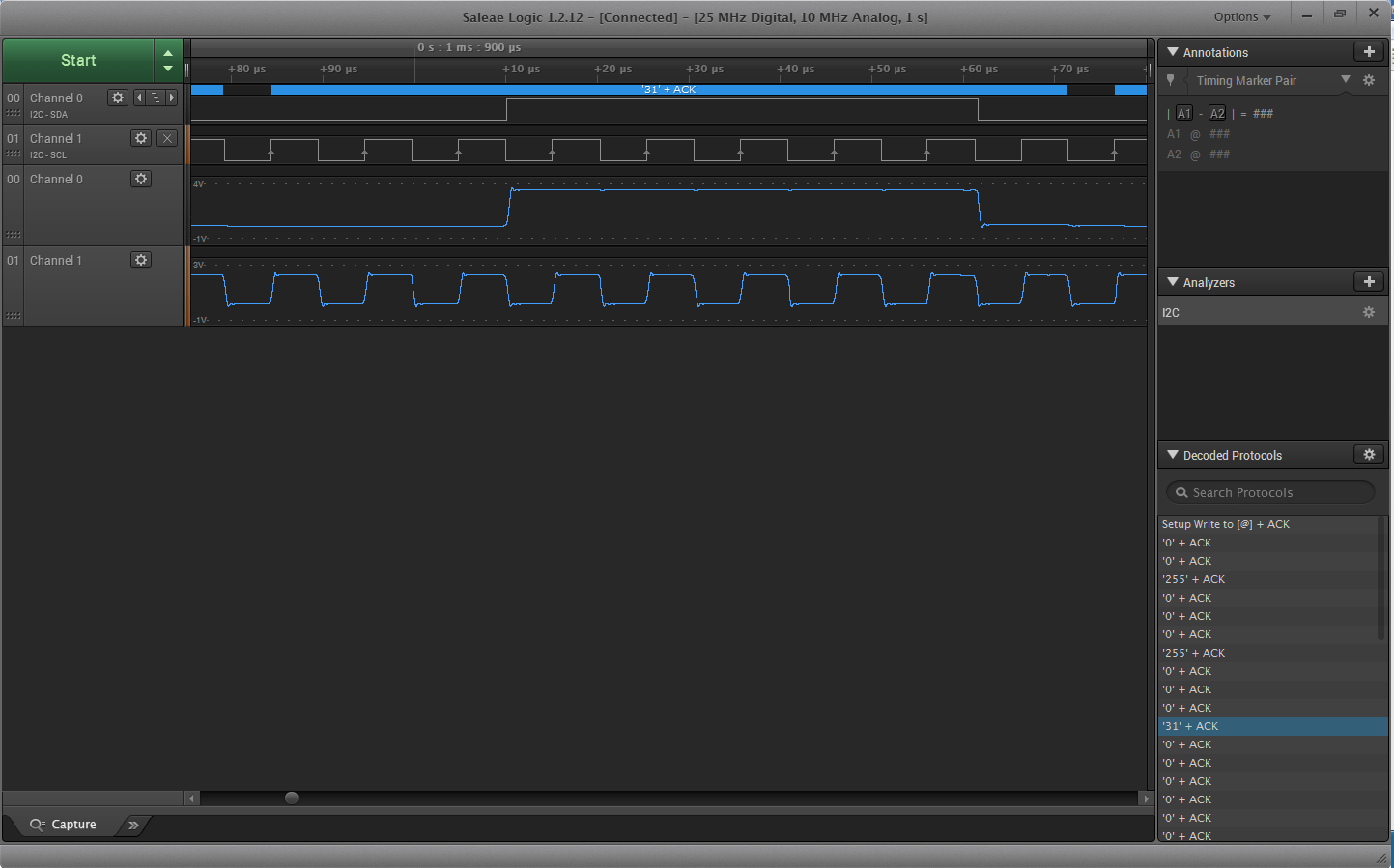
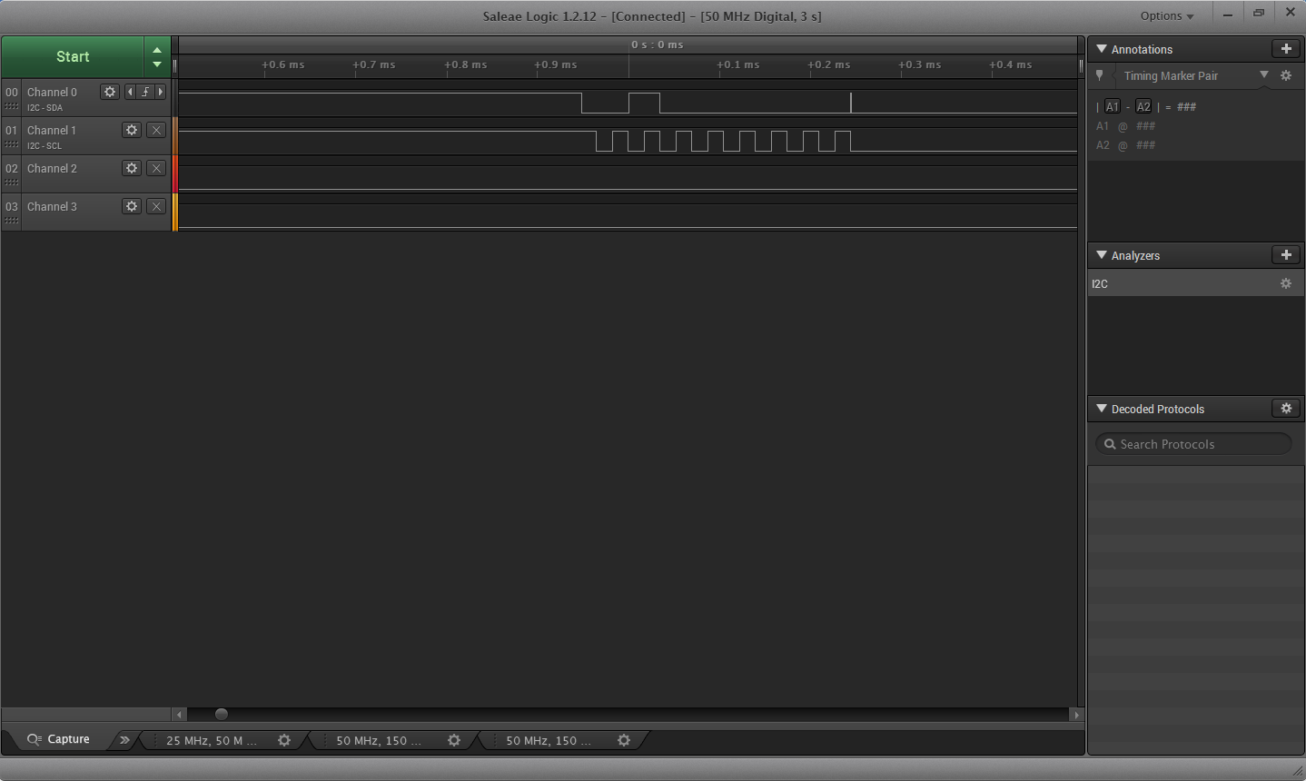
Using polling, I've verified that the corresponding TX flag is being set and with a logic analyzer I verified that the slave acknowledges each byte. I can't understand why the ISR won't run. Relevant code blocks below:
USCI_B initialization block:
// Initialize USCI_B0 to standard speed I2C master mode. Pins are already assigned to SCL and SDA. UCB0CTL0 = UCMST | UCMODE_3 | UCSYNC; // 7-bit addressing, single master UCB0CTL1 |= UCSSEL_2 | UCTR | UCSWRST; // Transmitter mode, sourced from SMCLK UCB0BR1 = 0; // set the upper baud rate register to 0 UCB0BR0 = I2C_CLOCK_DIV; // 100KHz bus frequency, sourced from 16MHz SMCLK divided by 40 UCB0STAT = 0; // reset state change flags IFG2 &= ~(UCB0TXIFG | UCB0RXIFG); // reset the transmit and recieve flags UCB0I2CIE = UCNACKIE | UCSTPIE | UCSTTIE | UCALIE; // Enable interrupts for all bus state changes IE2 |= UCB0RXIE | UCB0TXIE; // Enable interrupts for I2C receive and transmit (transmit enabled on default) UCB0I2CSA = 0; // Initialize slave address to 0 UCB0CTL1 &= ~UCSWRST; // Reset UCSWRST, starting I2C communication
__bis_SR_register(GIE); // enable global interrupts
I2C Bus Initialization loop:
while (~status & MCP23018_INIT) { // while the MCP23018 is NOT initialized if (IFG2 & UCB0TXIFG || interrupt_test > 0) { // if it is time to load the TXBUFFER if (~status & MCP23018_INIT) { // if the MCP23018 is NOT initialized: if (i2c_i > OLATB+1) { // if this is the bit after the last register: i2c_i = 0; // reset i2c iterator UCB0CTL1 |= UCTXSTP; // transmit STOP signal status |= MCP23018_INIT; } UCB0TXBUF = MCP23018_INIT_DATA[i2c_i]; // put the corresponding byte from init data array into the tx buffer i2c_i++; // increment the i2c iterator } } else if (UCB0I2CSA == 0) { // otherwise: if the slave address is 0 UCB0I2CSA = MCP23018_OPCODE; // load slave address+0 for write mode UCB0CTL1 |= UCTXSTT; // send I2C start condition } else if (UCB0STAT & UCNACKIFG) { // if NACK was recieved UCB0STAT &= ~UCNACKIFG; // clear the flag i2c_i = 0; // reset address iterator to 0 UCB0CTL1 |= UCTXSTT; // set a start condition IFG2 |= UCB0TXIFG; // set the TX flag }
//__bis_SR_register(LPM0_bits + GIE); // turn off the CPU to save power, global interrupt enabled } P1OUT |= BIT0; // light up LED1 when initialized
I2C Data ISR:
#pragma vector=USCIAB0TX_VECTOR // since the USCI_B is in I2C mode, this is the I2C data ISR __interrupt void USCIAB0TX_ISR(void) { // when the USCI_B TX register is empty or RX register is full __bic_SR_register_on_exit(LPM0_bits); // clear the bits to wake up the CPU } // return to the main loop
I2C State ISR:
#pragma vector=USCIAB0RX_VECTOR // since the USCI_B is in I2C mode, this is the I2C state ISR __interrupt void USCIAB0RX_ISR(void) { // when the I2C state changes __bic_SR_register_on_exit(LPM0_bits); // clear the bits to wake up the CPU } // return to the main loop
Oops, I forgot to include the logic analyzer screenshot, here it is: running at 100KHz, the I2C bus works exactly as expected and the MCP23018 is initialized to the correct state, however the ISRs were no help. I had to a while loop to not only to initialize the MCP, but to send and receive data from it.
This was the result of the code below:
/* --COPYRIGHT--,BSD_EX
* Copyright (c) 2012, Texas Instruments Incorporated
* All rights reserved.
*
* Redistribution and use in source and binary forms, with or without
* modification, are permitted provided that the following conditions
* are met:
*
* * Redistributions of source code must retain the above copyright
* notice, this list of conditions and the following disclaimer.
*
* * Redistributions in binary form must reproduce the above copyright
* notice, this list of conditions and the following disclaimer in the
* documentation and/or other materials provided with the distribution.
*
* * Neither the name of Texas Instruments Incorporated nor the names of
* its contributors may be used to endorse or promote products derived
* from this software without specific prior written permission.
*
* THIS SOFTWARE IS PROVIDED BY THE COPYRIGHT HOLDERS AND CONTRIBUTORS "AS IS"
* AND ANY EXPRESS OR IMPLIED WARRANTIES, INCLUDING, BUT NOT LIMITED TO,
* THE IMPLIED WARRANTIES OF MERCHANTABILITY AND FITNESS FOR A PARTICULAR
* PURPOSE ARE DISCLAIMED. IN NO EVENT SHALL THE COPYRIGHT OWNER OR
* CONTRIBUTORS BE LIABLE FOR ANY DIRECT, INDIRECT, INCIDENTAL, SPECIAL,
* EXEMPLARY, OR CONSEQUENTIAL DAMAGES (INCLUDING, BUT NOT LIMITED TO,
* PROCUREMENT OF SUBSTITUTE GOODS OR SERVICES; LOSS OF USE, DATA, OR PROFITS;
* OR BUSINESS INTERRUPTION) HOWEVER CAUSED AND ON ANY THEORY OF LIABILITY,
* WHETHER IN CONTRACT, STRICT LIABILITY, OR TORT (INCLUDING NEGLIGENCE OR
* OTHERWISE) ARISING IN ANY WAY OUT OF THE USE OF THIS SOFTWARE,
* EVEN IF ADVISED OF THE POSSIBILITY OF SUCH DAMAGE.
*
*******************************************************************************
*
* MSP430 CODE EXAMPLE DISCLAIMER
*
* MSP430 code examples are self-contained low-level programs that typically
* demonstrate a single peripheral function or device feature in a highly
* concise manner. For this the code may rely on the device's power-on default
* register values and settings such as the clock configuration and care must
* be taken when combining code from several examples to avoid potential side
* effects. Also see www.ti.com/grace for a GUI- and www.ti.com/msp430ware
* for an API functional library-approach to peripheral configuration.
*
* --/COPYRIGHT--*/
//******************************************************************************
// MSP430G2xx3 Demo - USCI_B0 I2C Master TX single bytes to MSP430 Slave
//
// Description: This demo connects two MSP430's via the I2C bus. The master
// transmits to the slave. This is the master code. It continuously
// transmits 00h, 01h, ..., 0ffh and demonstrates how to implement an I2C
// master transmitter sending a single byte using the USCI_B0 TX interrupt.
// ACLK = n/a, MCLK = SMCLK = BRCLK = default DCO = ~1.2MHz
//
// *** to be used with "msp430g2xx3_uscib0_i2c_07.c" ***
//
// /|\ /|\
// MSP430G2xx3 10k 10k MSP430G2xx3
// slave | | master
// ----------------- | | -----------------
// -|XIN P1.7/UCB0SDA|<-|---+->|P1.7/UCB0SDA XIN|-
// | | | | |
// -|XOUT | | | XOUT|-
// | P1.6/UCB0SCL|<-+----->|P1.6/UCB0SCL |
// | | | |
//
// D. Dang
// Texas Instruments Inc.
// February 2011
// Built with CCS Version 4.2.0 and IAR Embedded Workbench Version: 5.10
//******************************************************************************
#include <msp430.h>
unsigned char TXData;
unsigned char TXByteCtr;
int main(void)
{
WDTCTL = WDTPW + WDTHOLD; // Stop WDT
P1SEL |= BIT6 + BIT7; // Assign I2C pins to USCI_B0
P1SEL2|= BIT6 + BIT7; // Assign I2C pins to USCI_B0
UCB0CTL1 |= UCSWRST; // Enable SW reset
UCB0CTL0 = UCMST + UCMODE_3 + UCSYNC; // I2C Master, synchronous mode
UCB0CTL1 = UCSSEL_2 + UCSWRST; // Use SMCLK, keep SW reset
UCB0BR0 = 40; // fSCL = SMCLK/12 = ~100kHz
UCB0BR1 = 0;
UCB0I2CSA = 32; // Slave Address is 32
UCB0CTL1 &= ~UCSWRST; // Clear SW reset, resume operation
IE2 |= UCB0TXIE; // Enable TX interrupt
TXData = 0x00; // Holds TX data
while (1)
{
TXByteCtr = 1; // Load TX byte counter
while (UCB0CTL1 & UCTXSTP); // Ensure stop condition got sent
UCB0CTL1 |= UCTR + UCTXSTT; // I2C TX, start condition
__bis_SR_register(CPUOFF + GIE); // Enter LPM0 w/ interrupts
// Remain in LPM0 until all data
// is TX'd
TXData++; // Increment data byte
}
}
//------------------------------------------------------------------------------
// The USCIAB0TX_ISR is structured such that it can be used to transmit any
// number of bytes by pre-loading TXByteCtr with the byte count.
//------------------------------------------------------------------------------
#if defined(__TI_COMPILER_VERSION__) || defined(__IAR_SYSTEMS_ICC__)
#pragma vector = USCIAB0TX_VECTOR
__interrupt void USCIAB0TX_ISR(void)
#elif defined(__GNUC__)
void __attribute__ ((interrupt(USCIAB0TX_VECTOR))) USCIAB0TX_ISR (void)
#else
#error Compiler not supported!
#endif
{
if (TXByteCtr) // Check TX byte counter
{
UCB0TXBUF = TXData; // Load TX buffer
TXByteCtr--; // Decrement TX byte counter
}
else
{
UCB0CTL1 |= UCTXSTP; // I2C stop condition
IFG2 &= ~UCB0TXIFG; // Clear USCI_B0 TX int flag
__bic_SR_register_on_exit(CPUOFF); // Exit LPM0
}
}
From the logic analyzer it looks like the MSP took a nap and never woke up. Could this be the behavior described by USCI29 in SLAZ440H?
**Attention** This is a public forum