This thread has been locked.
If you have a related question, please click the "Ask a related question" button in the top right corner. The newly created question will be automatically linked to this question.
Tool/software: Code Composer Studio
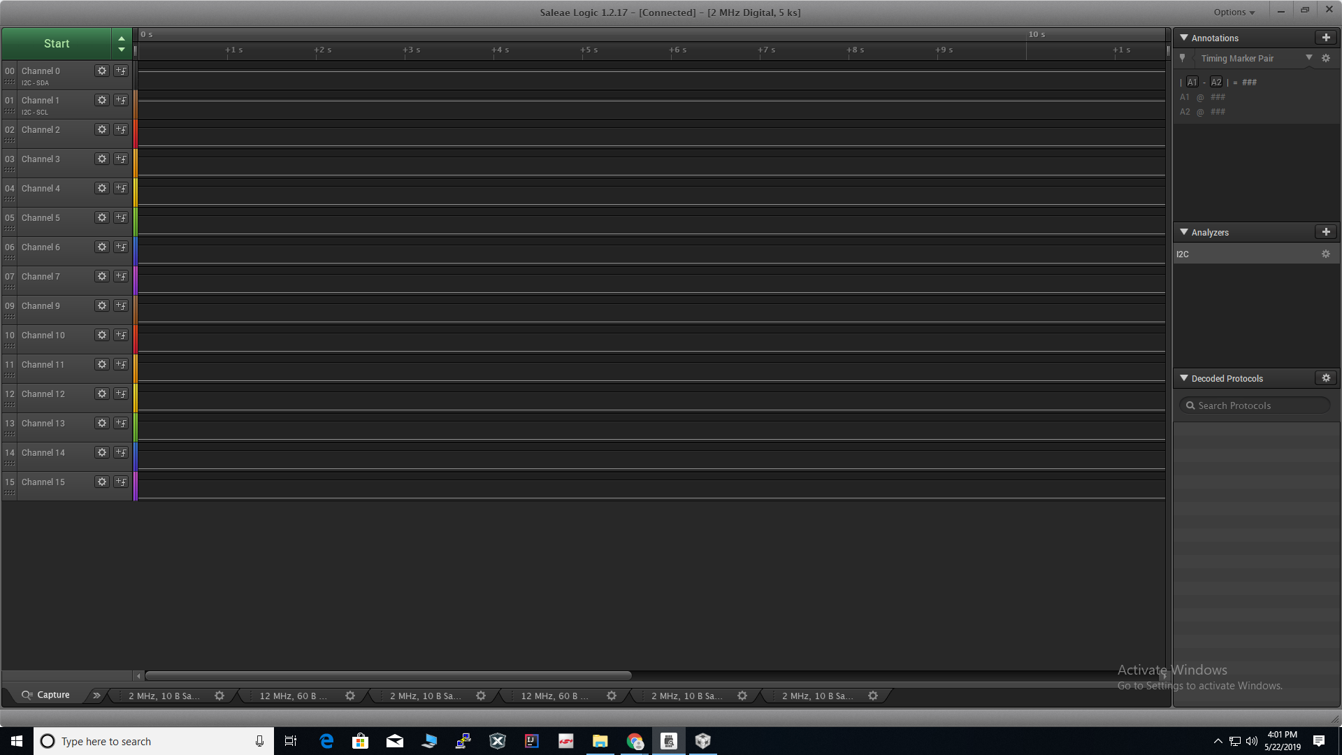
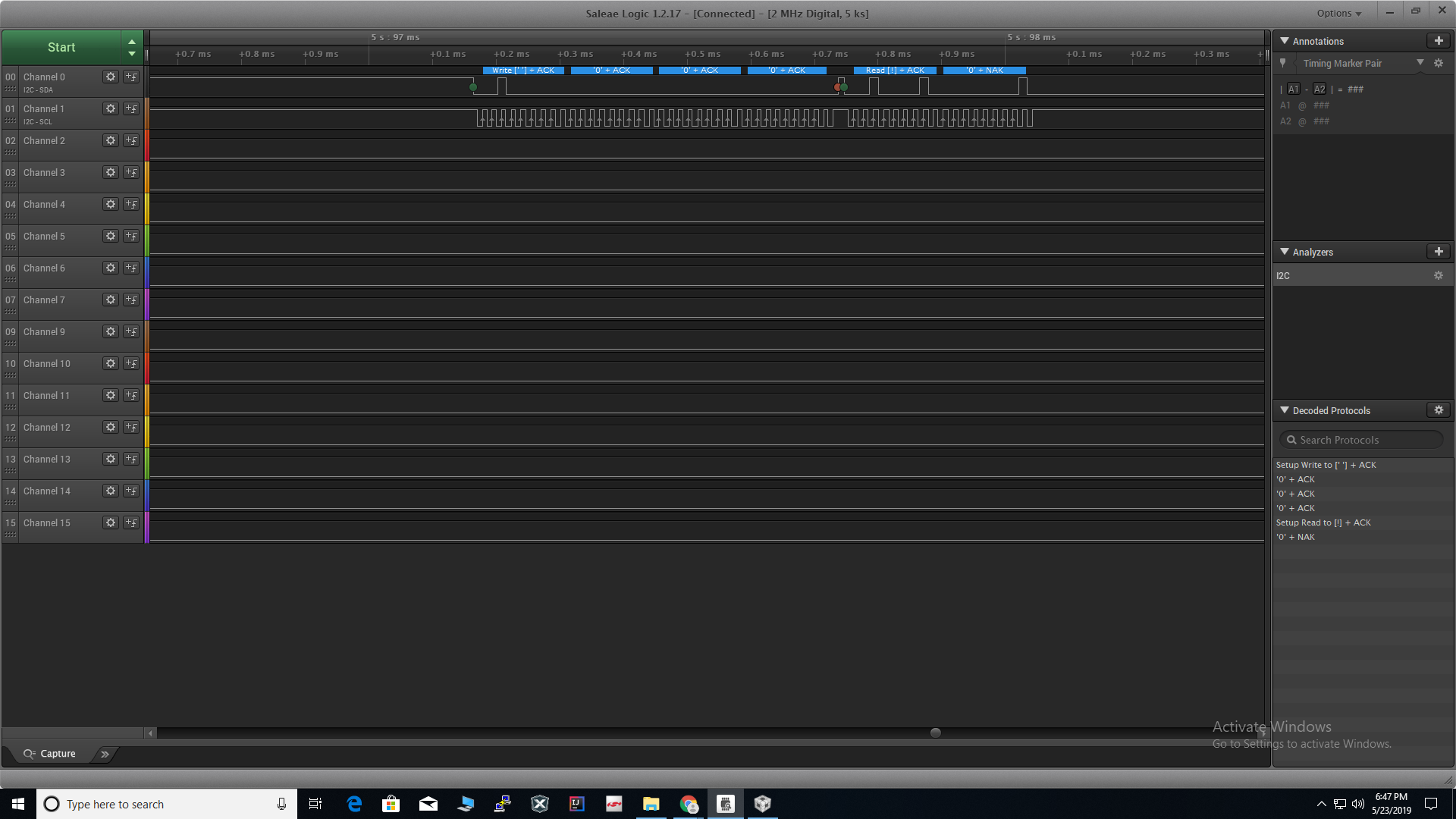
I am working on msp430fr2355 to communicate with veml6040(colour sensor) using i2c. I installed driver library provided in ccs resource explorer. I have written a program. But it is not working. the TxIFG0 flag is not being set. and the control is being stuck in a loop while polling for TxIFG flag. I even checked the output of SDA and SCL pins using logic analyzer. But there was nothing. the clock itself is not being generated by SCL. Below is my code. Can someone tell if something is wrong with it.
uint8_t RL;
uint8_t RH;
uint16_t t = 0;
EUSCI_B_I2C_initMasterParam i2cParam = {
EUSCI_B_I2C_CLOCKSOURCE_SMCLK,
1000000,
EUSCI_B_I2C_SET_DATA_RATE_100KBPS,
5,
EUSCI_B_I2C_NO_AUTO_STOP
};
int main(void)
{
EUSCI_B_I2C_initMasterParam* pmaster;
pmaster = &master;
EUSCI_B_I2C_initMaster(EUSCI_B1_BASE, pmaster);
EUSCI_B_I2C_setSlaveAddress(EUSCI_B1_BASE, 0x10);
P4SEL1 |= 0xC0; //Assigning pins 4.6 and 4.7 to I2C
EUSCI_B_I2C_enable(EUSCI_B1_BASE);
EUSCI_B_I2C_masterSendMultiByteStart(EUSCI_B1_BASE, 0xA5);
EUSCI_B_I2C_masterSendMultiByteFinish(EUSCI_B1_BASE, 0xA5);
EUSCI_B_I2C_masterSendMultiByteStart(EUSCI_B1_BASE, 0x08);
EUSCI_B_I2C_masterReceiveStart(EUSCI_B1_BASE);
RL = EUSCI_B_I2C_masterReceiveMultiByteNext(EUSCI_B1_BASE);
RH = EUSCI_B_I2C_masterReceiveMultiByteFinish(EUSCI_B1_BASE);
P1OUT = 0x00;
return 0;
}
when I run it. It is being Stuck in this loop :
//Poll for transmit interrupt flag.
while (!(HWREG16(baseAddress + OFS_UCBxIFG) & UCTXIFG)) ;
I tried using P4SEL0 |= 0xC0;. But it is still not working.
Actually it is not A5. It is 0x00, It is Command code for configuration register.
This is my code :
#include <msp430.h>
#include "driverlib.h"
uint8_t RL;
uint8_t RH;
uint16_t t = 0;
uint16_t i = 0;
EUSCI_B_I2C_initMasterParam master = {
EUSCI_B_I2C_CLOCKSOURCE_SMCLK,
1000000,
EUSCI_B_I2C_SET_DATA_RATE_100KBPS,
5,
EUSCI_B_I2C_NO_AUTO_STOP
};
int main(void)
{
// stop watchdog timer
P1DIR = 0x01;
P1OUT = 0x01; // LED on
P4SEL0 |= BIT6 | BIT7;
EUSCI_B_I2C_initMasterParam* pmaster;
pmaster = &master;
EUSCI_B_I2C_disable(EUSCI_B1_BASE);
EUSCI_B_I2C_initMaster(EUSCI_B1_BASE, pmaster);
EUSCI_B_I2C_setSlaveAddress(EUSCI_B1_BASE, 0x10);
EUSCI_B_I2C_setMode(EUSCI_B1_BASE, EUSCI_B_I2C_TRANSMIT_MODE);
P4SEL1 |= 0xC0;
EUSCI_B_I2C_enable(EUSCI_B1_BASE);
i = UCB1CTLW0;
//EUSCI_B_I2C_setMode(EUSCI_B1_BASE, EUSCI_B_I2C_TRANSMIT_MODE);
EUSCI_B_I2C_masterSendMultiByteStart(EUSCI_B1_BASE, 0x00); // command code for configuration register
EUSCI_B_I2C_masterSendMultiByteFinish(EUSCI_B1_BASE, 0x00); // value to be written into configuration register
EUSCI_B_I2C_masterSendMultiByteStart(EUSCI_B1_BASE, 0x08); // command code for red register
//EUSCI_B_I2C_setMode(EUSCI_B1_BASE, EUSCI_B_I2C_RECEIVE_MODE);
EUSCI_B_I2C_masterReceiveStart(EUSCI_B1_BASE); // start receiving data from Red register
RL = EUSCI_B_I2C_masterReceiveMultiByteNext(EUSCI_B1_BASE); // LSB(low byte) of red register
RH = EUSCI_B_I2C_masterReceiveMultiByteFinish(EUSCI_B1_BASE); //MSB(high byte) of red register
P1OUT = 0x00; // LED off
return 0;
}
> PM5CTL0 &= ~LOCKLPM5; // Engage GPIOs
I have added this statement. But I am still getting the same problem. The clock is not being generated on the SCL pin.
I even connected pullup resistors between SCL SDA pins and 3.3V. I tried with both 9.2K and 4.7K resistors.
I am uploading the picture of the scope when I run the code. I am also uploading the code.
#include <msp430.h> #include "driverlib.h" uint8_t RL; uint8_t RH; uint16_t t = 0; uint16_t i = 0; EUSCI_B_I2C_initMasterParam master = { EUSCI_B_I2C_CLOCKSOURCE_SMCLK, 1000000, EUSCI_B_I2C_SET_DATA_RATE_100KBPS, 5, EUSCI_B_I2C_NO_AUTO_STOP }; int main(void) { WDTCTL = WDTPW | WDTHOLD; // stop watchdog timer PM5CTL0 &= ~LOCKLPM5; //Engage GPIOs P1DIR = 0x01; P1OUT = 0x01; // LED on //P4DIR = 0x00; //P4SEL1 |= 0xC0; P4SEL0 |= 0xC0; P4REN |= 0xC0; //P4OUT |= 0xC0; // EUSCI_B_I2C_remapPins(EUSCI_B1_BASE, EUSCI_B_I2C_REMAP_PINS_TRUE); EUSCI_B_I2C_initMasterParam* pmaster; pmaster = &master; //EUSCI_B_I2C_disable(EUSCI_B1_BASE); EUSCI_B_I2C_initMaster(EUSCI_B1_BASE, pmaster); EUSCI_B_I2C_setSlaveAddress(EUSCI_B1_BASE, 0x10); //EUSCI_B_I2C_setMode(EUSCI_B1_BASE, EUSCI_B_I2C_TRANSMIT_MODE); P4SEL1 |= 0xC0; EUSCI_B_I2C_enable(EUSCI_B1_BASE); //__delay_cycles(10000); //EUSCI_B_I2C_setMode(EUSCI_B1_BASE, EUSCI_B_I2C_TRANSMIT_MODE); //EUSCI_B_I2C_masterSendMultiByteStart(EUSCI_B1_BASE, 0x00); // command code for configuration register EUSCI_B_I2C_masterSendSingleByte(EUSCI_B1_BASE, 0x00); EUSCI_B_I2C_masterSendMultiByteFinish(EUSCI_B1_BASE, 0x00); // value to be written into configuration register EUSCI_B_I2C_masterSendMultiByteStart(EUSCI_B1_BASE, 0x08); // command code for red register //EUSCI_B_I2C_setMode(EUSCI_B1_BASE, EUSCI_B_I2C_RECEIVE_MODE); EUSCI_B_I2C_masterReceiveStart(EUSCI_B1_BASE); // start receiving data from Red register RL = EUSCI_B_I2C_masterReceiveMultiByteNext(EUSCI_B1_BASE); // LSB(low byte) of red register RH = EUSCI_B_I2C_masterReceiveMultiByteFinish(EUSCI_B1_BASE); //MS(high byte) of red register P1OUT = 0x00; // LED off return 0; }
Ok I will try that.
I am using CCS.
My problem is that, if I debug and run the code, it is not working i.e. no clock is being generated.
It is working only if I flash it on to the board and then remove the USB and plug it back.
When I run it like this I cannot see variables that I am using to receive the data from the slave.
Can you suggest something for that.
**Attention** This is a public forum