This thread has been locked.

If you have a related question, please click the "Ask a related question" button in the top right corner. The newly created question will be automatically linked to this question.

MSP-EXP430FR6989: Square wave pulse counter

Part Number: MSP-EXP430FR6989
Other Parts Discussed in Thread: MSP430FR6989

I'm trying to count pulses from a 500 kHz square wave signal using the MSP-EXP430FR6989 board. I'm trying to send the square wave as an external clock source to P1.4/TA1.0 which captures on a falling edge and increments the variable "StoredCount" every 100 pulses. For some reason, the pulses aren't being counted because StoredCount always reads 0. Here is the code that I have so far:

#include <msp430.h>


volatile unsigned int StoredCount = 0;


int main(void)
{
WDTCTL = WDTPW | WDTHOLD;

P1DIR &= ~BIT0;
P1SEL0 |= BIT4;

TA1CCR0 = 100;
TA1CCTL0 |= CCIE + CCIS_0 + CM_2 + CAP;
TA1CTL |= TASSEL_0;

_BIS_SR(GIE);

while(1)
{

TA1CTL |= MC1;
while(StoredCount != 1000000);
TA1CTL &= ~MC1;
StoredCount = 0;
TA1R = 0;
}

return 0;
}

#pragma vector = TIMER1_A0_VECTOR
__interrupt void Timer1_A0_ISR (void)
{
StoredCount++;
}

Currently I'm just monitoring the StoredCount variable using the debugger in CCS cloud and StoredCount is always 0 no matter how long I run it for.  All of this is part of a larger project to build a frequency, but I'm just having trouble counting pulses from an external signal. 

Any help would be greatly appreciated.

  • Hi Eli,

    I see that you're sourcing the timer from TA1CLK:

    Eli Mueller said:
    TA1CTL |= TASSEL_0;

    This would mean you are supplying an external digital clock to the timer and would require the setup of P5.2 as seen below:

    I don't think this was you're intention and therefore the timer is never actually counting. Can you try sourcing the timer from SMCLK?

    Also I noticed that StoredCount is an unsigned int which is 16 bits on the MSP430. The largest number a 16 bit unsigned intergar can be is 65536 and I see you're comparing it to 1000000. This statement will always return false because overflow will occur before the StroedCount reaches 1000000. I recommend using stdint.h and making it a 32 bit integer with uint32_t.

    Best regards, 

    Caleb Overbay

  • Thanks for the correction on the size of the StoredCount variable. But I'm still having trouble getting a pulse count. I guess I don't understand exactly what it means to supply an external clock to the timer. Currently, I have a function generator that's putting out a 500 kHz square wave of roughly 0-5V and I want to count say 10000 of those square pulses using the launchpad. I thought that I could do this by treating the square wave as an external clock source (this is why I have TA1CTL |= TASSEL0) by sending the signal to Timer A1 on P1.4/TA1.0 and just have timerA capture each pulse on the rising edge. Is it not correct to think of the square wave as an external clock source like this? If so what is the best way of counting the square pulses. I don't necessarily need to be counting for a certain duration just until the StoredCount variable reaches a certain value.
  • Hi Eli,

    The square wave you're applying to P1.4 is not the timer's clock source. It's the signal that triggers a timer capture event. The timer still needs to be source from something so that it can count and operate correctly.

    You are selecting P1.4 as the trigger signal by setting the CCIS_0 bits in TA1CCTL0. I suggest setting SMCLK as your timer source by setting TA1CTL |= TASSEL_2;

    You can also find an example of using TimerA to determine a square wave's frequency in the example msp430fr69xx_ta0_capture.c that can be found here.

    Best regards,

    Caleb Overbay

  • Hi Eli,

    I hope you have some knowledge of CCS, C language, and MSP430, or I fear the following may not make much sense........

    Taking Caleb's good advice a bit further, and assuming your final goal is to measure that nominal 500KHz frequency, here's some other info to consider:

    0- it is definitely possible to measure input frequencies with the MSP Timer A. It is a bit tricky on the 6989 LP since the TA0&1 CLK input pins are difficult to access without soldering wires.

    1- your input signal amplitude (you mention 0 to 5 volt square) must be below the MSP Vcc level ! so, 0-3v is better. Or bad things will happen.

    2- Instead of P5.2 / function TA1CLK; consider using either : P1.1 / TA1CLK (Button 1 on LP) -or- P1.2 TA0CLK (Button 2).
    All this can be found in the 6989 LP user guide (SLAU627A–May 2015–Revised July 2015), schematic . p.29. Fig 16. Sheet 1/6. Top left corner. Choose P1.1 or 1.2, then solder your wire to Button 1 or 2 respectively. (Note - P5.2 goes to an LCD segment)

    3- Then set up P1.1 or 1.2 using the PSEL bits. Now you have an ext clk that can increment TAR 0 or 1.

    That's the hardware. For the software, you have to decide what you want to measure and how to do that.

    4 a - simple and pretty good : Clear TAR, wait a gate interval, then read TAR.
    EG: if you wait 0.1 second, TAR will be 50,000 counts.
    Hint : your 'wait' can be generated by another timer.

    4 b - accurate, hardware measurement : with your ext 500khz incrementing TAR, use ACLK edge internally to capture a TAR_value_1. The very next ACLK edge gives TAR_value_2. Your frequency = the difference of these two.

    Hint : 6989 datasheet, table 6-10 or 6-11. Column 'Device Input Signal'. Two entries: TAnCLK; ACLK (internal).
    n is for TA0 or TA1

    reference:
    - book - check online - MSP430 Microcontroller Basics John H. Davies - Great to have AND excellent on MSP TA timer examples.
    - 8.4.3 Measurement of Frequency: Comparison of SMCLK and ACLK (starting page 312) It uses SMLK, but ACLK is possible in 689 as in 4b, above.


    4 c - Period measurement. This is beyond the scope, but you'd measure SMCLK into TAR between two successive rising edges of your 500khz external signal connected as a 'capture input'.
    This may be what Caleb was pointing to.
    Extend this idea by capturing on the 1st 500khz edge - letting more edges go by - then capturing TAR on the last edge. The accumulated SMCLK is your 500khz period. Freq = 1 / period.


    5 - there are other possibilities, as you're likely aware.....


    If all this is confusing, just keep at it. The TA timer (and cousin TB timer) are very useful.

    good luck.
  • Thanks both Otto and Caleb. I think I'm understanding how I need to setup the input signal and the timer A clock now. I have fixed up my code now to try and do what Caleb was suggesting by sourcing from SMCLK and setting up P1.4/TA1.0 to capture the input square pulses. For some reason I'm still not getting any counts in the variable StoredCount. My code is below:

    #include <msp430.h>

    volatile unsigned int StoredCount = 0;


    int main(void)
    {
    WDTCTL = WDTPW + WDTHOLD; // stop watchdog timer

    // setup pin 1.4/TA1.0
    P1DIR &= ~BIT0;
    P1SEL0 |= BIT4;

    PM5CTL0 &= ~LOCKLPM5;

    TA1CCTL0 |= CCIE + CCIS_0 + CM_1 + CAP; // interrupt enable
    // capture off of CCI0A
    // capture rising edge
    // capture mode

    TA1CTL |= TASSEL_2; // source timer A1 from SMCLK

    _BIS_SR(GIE);

    while(1)
    {
    TA1CTL |= MC1; // Start timer
    while(StoredCount != 1000);
    TA1CTL &= ~MC1; // Stop timer
    StoredCount = 0; // Zero StoredCount
    TA1R = 0; // Zero Timer_A1 register
    }

    return 0;
    }

    #pragma vector = TIMER1_A0_VECTOR
    __interrupt void Timer1_A0_ISR (void)
    {
    StoredCount++;
    }

    I have a feeling that my problem is in how I'm setting up pin1.4 with the PxSEL bits. I think I want to setup the third peripheral function on P1.4 if I'm understanding the documentation that I added below.

    Screen Shot 2017-08-17 at 11.13.09 AM.pdf

    Or possibly the problem is in my start timer and stop timer commands not sure where but I feel like I'm getting close. Right now I just have a ~50 Hz 0-3V square wave going into P1.4 just to see if I can get anything counted on P1.4 but eventually I would like to count pulses around 500 kHz as I mentioned before.

    Thanks

  • Hi,

    We'd like to help, but now I'm not certain precisely what it is you want to measure ;)
    Maybe Caleb got it?

    In any case, that book reference mentioned earlier is quite good on Timer A matters.
    >>>>> reference:
    - book - check online - MSP430 Microcontroller Basics John H. Davies - Great to have AND excellent on MSP TA timer examples.
    - 8.4.3 Measurement of Frequency: Comparison of SMCLK and ACLK (starting page 312) It uses SMLK, but ACLK is possible in 689 as in 4b, above. <<<<


    Apart from that, here's an I/O issue in your code; and a tip at #2 :

    1---- datasheet Table 6-18. Port P1 (P1.4 to P1.7) Pin Functions

    // setup pin 1.4/TA1.0
    P1DIR &= ~BIT0; .............. you want p1.4, not this one
    P1SEL0 |= BIT4; ................ you want both psel 0 1 set ...... this selects TA1.CCI0A

    now, P1.4 should act as a CC input.


    2---- interrupt occurrence and vector value:

    - in CCS debug, a breakpoint in the interrupt service routine will confirm that ints are really happening and what the vector value is.
    - then confirm this against desired values. check FR68 Family Boom, Table 16-8. TAxIV Register Description


    That's about it from my side !

    you're close ! try it, and good luck !
  • Hi Eli,

    It looks like you're setting up P1.4 incorrectly. You should be setting P1DIR.x to 0, P1SEL1.x to 1 and P1.SEL0.x to 1:

    Best regards, 

    Caleb Overbay

  • Yeah the problem was with how I was setting up P1.4. My code is working now and I can count the square pulses so thanks. I'm just having an issue with calibrating the DCO frequency setting. With the DCO set at the default 1MHz, I can only count pulses up to ~50kHz. So I tried setting the DCO frequency to 16MHz but I don't think it's being set to 16MHz. The first few lines that are relevant to setting up the dco are below:

    WDTCTL = WDTPW + WDTHOLD; // stop watchdog timer


    CSCTL0_H = CSKEY >> 8; // Unlock CS registers
    CSCTL1 |= DCORSEL; // Set DCORSEL = 1
    CSCTL1 |= DCOFSEL_4; // set CDOFSEL = 4
    CSCTL2 |= SELS__DCOCLK; // Select SMCLK = DCO
    CSCTL3 |= DIVS_0; // divide by 1
    CSCTL0_H = 0x00; // Lock CS module (use byte mode to upper byte)

    __delay_cycles(1000); // Allow clock system to settle


    // setup pin 1.4/TA1.0
    P1DIR &= ~BIT4;
    P1SEL1 |= BIT4;
    P1SEL0 |= BIT4;

    These settings should be correct according to the documentation:

    These settings allow me to count square pulses up to ~150 kHz but I'm hoping to be able to count up to 500kHz. To check if these settings were properly setting the DCO frequency to 16MHz, I just used the TI sample code msp430fr69xx_ta0_capture.c and copy and pasted the same clock system control (CSCTL) settings from my code to set the dco. In this sample code, the period of the VLO clock (~9.4kHz) is captured by counting the DCO on SMCLK. When set at the default, the program counts about 111 DCO counts every VLO capture (9.4kHz * 111 ~1MHz) so that is accurate. But when I try setting the DCO to 16MHz with the CSCTL lines from my code I find that the program counts about 330 counts every VLO capture so the DCO is not being set to 16MHz (9.4 * 330 ~ 3 MHz). Any ideas on what I could be doing wrong? Thanks a ton for your help. 

  • Hi Eli, 

    Glad to here things are "working" for you. It looks like you've setup the DCO appropriately to run SMCLK at 16MHz. To double check it's frequency, can you output the SMCLK using the following code an observe it's frequency using an oscilloscope?

      P7DIR |= BIT4;
      P7SEL0 |= BIT4;                           // Output SMCLK
      P7SEL1 |= BIT4;

    Best regards, 

    Caleb Overbay

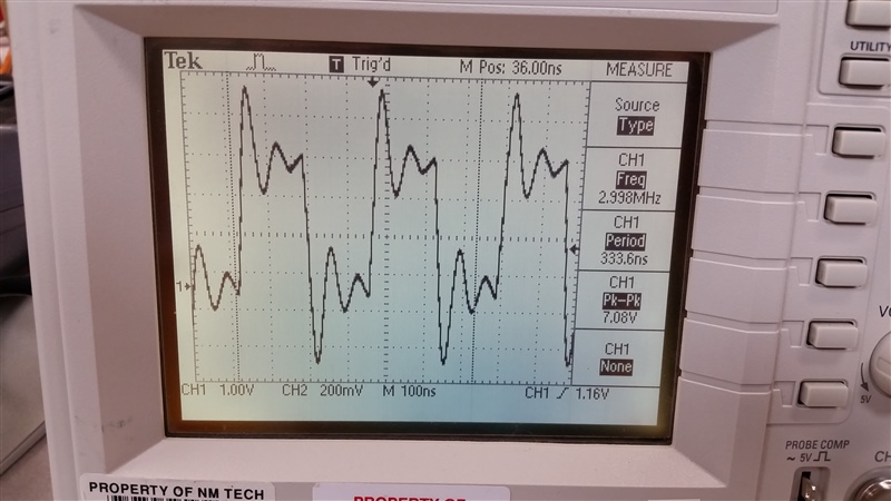
  • I added the code you suggested and then measured the frequency off of P7.4 near the LCD. Below is a pic of the oscilloscope output with my code having the same settings as my previous post:

    I'm very new to these launchpads so I really don't know if those oscillations are supposed to be happening but they seem fairly large.

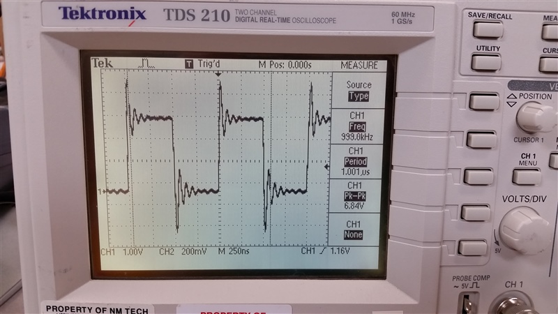
    But then when I comment out the "CSCTL1 |= DCORSEL;" line in my code, the frequency goes to 1MHz whether DCOFSEL is set to 0 or 4 which seems wrong (with large oscillations again). A pic of the oscilloscope with the DCORSEL line commented out and DCOFSEL set to 0 is shown below.

    Thanks for your help Caleb

  • Hi Eli,

    I didn't notice that P7.4 is connected to the LCD on the MSP-EXPFR6989 and this could be affecting the output signal. Can you try instead ouput MCLK to pin 4.0 using the following code:

    P4DIR |= BIT0;
    P4SEL0 |= BIT0;                           // Output MCLK
    P4SEL1 |= BIT0;

    With your clock setup MCLK should be the same frequency as SMCLK. This way you'll be able to accurately measure the SMCLK frequency with no interference from the LCD. 

    Best regards, 
    Caleb Overbay

  • I used the code you posted and measured MCLK out of P4.0 and the same thing happens. The frequency is 1MHz when DCORSEL = 0 and the frequency is 3 MHz when DCORSEL =1 regardless of whether DCOFSEL is 0 or 4.

    Eli

  • Hi Eli,

    The issue is that you are using "|=" on the CSCTL1 and CSCTL3 registers. If you look at these registers in the user's guide, you'll see that they are setup to default values on startup. To properly change these to the values you're trying to, you need to either clear the bits you are trying to set before changing them or switch to setting the register with an "=".

    Best regards,
    Caleb Overbay
  • Ok so replacing "|=" with  "=" on the CSCTL1 and CSCTL3 registers got the DCO running up to 5.3 MHz with DCOFSEL = 4. I then set DCOFSEL =6 and that got it up to 8 MHz. So I'm wondering why the DCO isn't running at 16 MHz. From what I just said it seems like maybe DCORSEL isn't being set to 1 like I think it is in order for the DCO to get to 16 MHz. However, I looked into calibrating the DCO for the msp430fr6989 a little more and found something about needing a wait state if the MCLK is going higher than 8MHz. Here's the link

    I tried to include 1 wait state as suggested in that link. I just added one line in my code using NWAITS on the FRCTL0 register as shown in my code below:

    WDTCTL = WDTPW + WDTHOLD; // stop watchdog timer

    FRCTL0 = NWAITS_1;  // 1 wait state

    CSCTL0_H = CSKEY >> 8;  // Unlock CS registers
    CSCTL1 = DCORSEL;  // Set DCORSEL = 1
    CSCTL1 = DCOFSEL_4;  // set DCOFSEL = 4
    CSCTL2 |= SELS__DCOCLK;  // Select SMCLK = DCO
    CSCTL3 = DIVS_1;  // divide by 1
    CSCTL0_H = 0x00;  // Lock CS module (use byte mode to upper byte)

    When I run my code with the FRCTL0 line I don't see anything on the oscilloscope. How can I get the DCO to run at 16 MHz? I'm almost there.

    Thanks,

    Eli

  • Hi Eli,

    You are overwriting the DCORSEL setting by performing back to back "=" operations on the CSCTL1 register. I recommend setting them in the same instruction with "CSCTL1 = DCORSEL | DCOFSEL_4;"

    Also, when setting MCLK > 8MHz you need wait states. You can find an example of this in the clocking examples found in TI Resource Explorer. This is not what was causing your issue in the first place, but it could  cause problems down the road.The most notable change you need to make in regards to wait states is including the password for the FRDTL0 register: "  FRCTL0 = FRCTLPW | NWAITS_1;"

    Best regards,

    Caleb Overbay

  • My code works and I can count pulses up to 700kHz now. Thanks a ton

**Attention** This is a public forum