This thread has been locked.

If you have a related question, please click the "Ask a related question" button in the top right corner. The newly created question will be automatically linked to this question.

MSP430FR5969: Timer pulse jitter is large

Part Number: MSP430FR5969


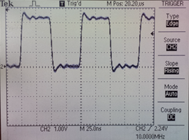
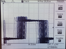
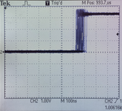
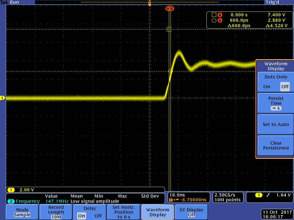
I am working on a product that requires low-jitter timing pulse with a 1ms period. I'm generating a pulse using MSP430FR5969 timer in compare mode, with no interrupt involved, with the timer set up to pulse the capture/compare reg. associated OUT bit. I am puzzled as to why I am seeing significant jitter in the periodic pulse. The jitter that I measure leading edge to trailing edge is approx. 15ns, and jitter measured leading edge to leading edge of next pulse is over 250ns along with some low-frequency drift.
I am wondering why the jitter is so large? The only relavant spec I found in the data sheet is the DCO jitter of 2ns. I am using the DCO at 16MHz as source for MCLK and SMCLK, and the timer source is SMCLK.

Here's my timer init code:

void tmrA0Init (void) {
    // configure P1.1 for use as TA0.2
    P1DIR  |= BIT1;
    P1SEL1 &= ~BIT1;
    P1SEL0 |= BIT1;

    TA0CCR0 = 1024;    // CCR0 drives high (reset/set mode)
    TA0CCR2 = 2048;    // drives TA0.2 low
    // Cap/comp 2
    TA0CCTL2 = CM_0 | CCIS_0 | CLLD_0 | OUTMOD_7 ;  // Reset/Set output mode, no interrupt
    TA0CTL = CNTL_0 | TASSEL__SMCLK | ID_0 | MC__CONTINUOUS;
}

Any insights into this jitter would be appreciated.

Thanks,

John

  • Hello John,

    Since the source of your timer clock is coming from the SMCLK, have you tried outputting the SMCLK to a GPIO pin and measuring the integrity of that signal? If you see jitter on that clock then that is the source of why the Timer has similar behavior. You will have to check the datasheet to see if this clock jitter is within the DCO operating specifications. For high accuracy applications, it is best to use a crystal.

    Best regards,

    Matt Calvo
  • Hi Matt,
    Yes, I set up to output SMCLK on P3.4 and I'm looking at the period jitter with a scope 100uS after the trigger point. The jitter is approx. 20ns, ignoring the slow drift that is also present (temperature effects?). I'm not sure how to relate such a measurement to either the jitter spec from the data sheet, or to the jitter that I see in the timer output over a 1ms period.
  • John,

    Here are 2 different threads about clock jitter and clock stabilization that may help you with the problems that you are seeing.

    1- MSP430F2132 internal oscillator jitter

    2- MSP430 Clock Stabilization

    Best regards,

    Matt Calvo

  • Hi Matt,
    I had seen those posts already, but it's not clear to me they apply to the MSP430FR5969. The posts refer to the DCO modulator and the FLL, and I see no reference to those modules for FR5969.
  • John,

    Could you please provide your code so that I can try to recreate the problem you are having on my end. If I can't recreate it then we can work back and forth to see what the difference is but if I can then I can work to loop in someone who can further assist.

    -Matt
  • I previously posted my timer init code.    Here's the remaining startup code from main:

    This the rest of the code in main:
    
    int main(void) {
        WDTCTL = WDTPW | WDTHOLD;	// Stop watchdog timer
        FRAMCtl_configureWaitStateControl(FRAMCTL_ACCESS_TIME_CYCLES_1);        // Add FRAM wait states for FR5969 running at 16MHz
        CS_setDCOFreq(CS_DCORSEL_1, CS_DCOFSEL_4);  // sets DCO to 16MHz, the max for FR5969 see DS table 5-6
        CS_initClockSignal(CS_SMCLK, CS_DCOCLK_SELECT, CS_CLOCK_DIVIDER_1); // SMCLK is 16 MHz
        CS_initClockSignal(CS_MCLK,  CS_DCOCLK_SELECT, CS_CLOCK_DIVIDER_1); // MCLK is 16 Mhz:  FRAM r/w is limited to 8 MHz so FRAM access needs wait states
        PMM_unlockLPM5();
        // set up P3.4 to monitor SMCLK
        P3DIR  |= BIT4;
        P3SEL1 |= BIT4;
        P3SEL0 &= ~BIT4;
        tmrA0Init (); 
        while (1) {
        	__no_operation;
        }
    	return 0;
    }
    

  • Your suggestion to route SMCLK to an IO pin was very helpful. I used an external 10MHz oscillator as input to HFXIN and configured to use that as a source. I measured the jitter on this ext. 10MHz input to be small, approx. 2ns.
    Using this external clock as source for MCLK and SMCLK, I measured the jitter of SMCLK to be approx. 50 ns.

    Is there any explanation for this large jitter on SMCLK? 


  • I now see that the scope trace shows SMCLK to be approx. 4.7MHz. That implies that my code to switch to ext. 10MHz osc. failed, and the fail-safe clock MODOSC is being used for SMCLK. I'll now need to figure out why the switch to ext. osc. failed.
  • John,

    I have played with example code for quite a while now and I think I found something that might apply to your implementation. The code below is set up to output a pulse on P1.1 with a 1ms period (This example is from the Resource Explorer and is called msp430fr59xx_ta0_16.c). I checked the output of this code on P1.1 and it should meet your jitter requirements. Please let me know if this works out for you.

    Best regards,

    Matt Calvo

    #include <msp430.h>
    
    int main(void)
    {
      WDTCTL = WDTPW | WDTHOLD;                 // Stop WDT
    
      // Configure GPIO
      P1DIR |= BIT0 | BIT1;                     // P1.0 and P1.1 output
      P1SEL0 |= BIT0 | BIT1;                    // P1.0 and P1.1 options select
    
      // Disable the GPIO power-on default high-impedance mode to activate
      // previously configured port settings
      PM5CTL0 &= ~LOCKLPM5;
    
      CSCTL0_H = CSKEY >> 8;                    // Unlock CS registers
      CSCTL1 = DCOFSEL_6;                       // Set DCO = 8MHz
      CSCTL2 = SELA__VLOCLK | SELS__DCOCLK | SELM__DCOCLK;// Set ACLK=VLO SMCLK=DCO
      CSCTL3 = DIVA__8 | DIVS__8 | DIVM__8;     // Set all dividers
      CSCTL0_H = 0;                             // Lock CS registers
    
      // Configure Timer0_A
      TA0CCR0 = 1000-1;                         // PWM Period
      TA0CCTL1 = OUTMOD_7;                      // CCR1 reset/set
      TA0CCR1 = 750;                            // CCR1 PWM duty cycle
      TA0CCTL2 = OUTMOD_7;                      // CCR2 reset/set
      TA0CCR2 = 250;                            // CCR2 PWM duty cycle
      TA0CTL = TASSEL__SMCLK | MC__UP | TACLR;  // SMCLK, up mode, clear TAR
    
      __bis_SR_register(LPM0_bits);             // Enter LPM0
      __no_operation();                         // For debugger
    }
  • Matt,

    I implemented the code you provided to generate a 1ms periodic pulse.   The jitter I am seeing with this code is approx. 100ns,  Is that what you would expect, given the jitter spec on the clock source DCO is 2ns?   In this scope trace I am triggering on the edge of the 1ms pulse and showing jitter on the following edge.  Is the jitter in your example proportional to the frequency used to clock the timer?  I am asking because I am using SMCLK sourced by DCO at 16MHz and I am seeing approx. 500ns of jitter over 4ms.

  • John,

    I just went to the lab and probed the timer and SMCLK signals and could not recreate what you are seeing. For the timer signal running at 1ms period, I am measuring a jitter of approximately 600ps and for the SMCLK running at 1MHz, I am measuring a jitter of approximately 1.2ns. Both of these measurements lie within the specification outlined in the datasheet.

    Are you using a launchpad to test your device? Are your trigger settings on your oscilloscope set up correctly?

    Best regards,

    Matt Calvo

  • John,

    Have you determined anything new with this post? If you have solved the issue or feel that my support has helped you determine the solution please select that my above post resolved your issue so that we can close this thread. Thanks!

    Best regards,

    Matt Calvo

**Attention** This is a public forum