This thread has been locked.
If you have a related question, please click the "Ask a related question" button in the top right corner. The newly created question will be automatically linked to this question.
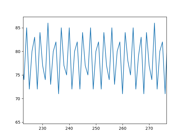
I am trying to read sensor data and send it to my computer through Bluetooth to be graphed. For testing purposes I am just trying to send a sine wave from a function generator before connecting my actual sensors, but I can only get a clean sine wave of about 2Hz to come through. My guess is that the issue is caused by differing speeds in the ADC sampling and UART transmission but I am pretty new to this so I can't figure out what my issue is.
#include <msp430g2553.h> /** * main.c */ int main(void) { WDTCTL = WDTPW | WDTHOLD; // stop watchdog timer //--------------------Disable Port 2---------------------// P2OUT &= 0x00; P2DIR &= 0x00; //------------------- Configure the Clocks -------------------// DCOCTL = 0; // Select lowest DCOx and MODx settings BCSCTL1 = CALBC1_1MHZ; // Set range DCOCTL = CALDCO_1MHZ; // Set DCO step + modulation //------------------- Configure pins--------------------------// P1SEL |= BIT1 + BIT2; // P1.1 UCA0RXD input P1SEL2 |= BIT1 + BIT2; // P1.2 UCA0TXD output P1DIR |= BIT3 + BIT4 + BIT5; //P1.3,1.4,1.5 set as outputs P1DIR &= ~BIT0 + ~BIT6; //P1.0,1.6 set as input //--------------------Configure ADC--------------------------// ADC10CTL0 &= ~ENC; ADC10CTL0 = ADC10SHT_1 + ADC10ON + ADC10SR + MSC + ADC10IE; ADC10CTL1 = INCH_0 + SHS_0 + ADC10DIV_0 + ADC10SSEL_0 + CONSEQ_0; ADC10AE0 |= BIT0; //------------ Configuring the UART(USCI_A0) ----------------// UCA0CTL1 |= UCSSEL_2 + UCSWRST; // USCI Clock = SMCLK,USCI_A0 disabled UCA0BR0 = 104; // 104 From datasheet table UCA0BR1 = 0; // -selects baudrate =9600,clk = SMCLK UCA0MCTL = UCBRS_1; // Modulation value = 1 from datasheet UCA0CTL1 &= ~UCSWRST; // Clear UCSWRST to enable USCI_A0 //---------------- Enabling the interrupts ------------------// IE2 |= UCA0TXIE + UCA0RXIE; // Enable the Tx and Rx interrupts _BIS_SR(GIE); // Enable the global interrupt while(1) { ADC10CTL0 &= ~ENC; while(ADC10CTL1 & ADC10BUSY) {} __low_power_mode_0(); ADC10CTL0 |= ENC + ADC10SC; } } //-----------------------------------------------------------------------// // Transmit and Receive interrupts // //-----------------------------------------------------------------------// #pragma vector = USCIAB0TX_VECTOR __interrupt void TransmitInterrupt(void) { UCA0TXBUF = ADC10MEM >> 2; // UART stored and sent in UCA0TXBUF IFG2 &= ~UCA0TXIFG; // Clear TX flag } #pragma vector = USCIAB0RX_VECTOR __interrupt void ReceiveInterrupt(void) { } #pragma vector = ADC10_VECTOR __interrupt void ADC10_ISR(void) { __low_power_mode_off_on_exit(); }
Thanks for you response. I tried the changes that you recommended but I'm still not getting a wave to come through well. I attached a picture of what the graph that I'm getting looks like from a 50 Hz sine wave. Is there maybe something I should do to make sure that each value sends before the ADC reads another value? The fastest wave that I will need to capture will only be around 10 Hz, so 480 Hz from 9600 baudrate should be more than sufficient. Thanks in advance!
#include <msp430g2553.h> /////////////////////ZERO IS INPUT///////////////////// /** * main.c */ int main(void) { WDTCTL = WDTPW | WDTHOLD; // stop watchdog timer //--------------------Disable Port 2---------------------// P2OUT &= 0x00; P2DIR &= 0x00; //------------------- Configure the Clocks -------------------// DCOCTL = 0; // Select lowest DCOx and MODx settings BCSCTL1 = CALBC1_1MHZ; // Set range DCOCTL = CALDCO_1MHZ; // Set DCO step + modulation //------------------- Configure pins--------------------------// P1SEL |= BIT1 + BIT2; // P1.1 UCA0RXD input P1SEL2 |= BIT1 + BIT2; // P1.2 UCA0TXD output P1DIR |= BIT3 + BIT4 + BIT5; //P1.3,1.4,1.5 set as outputs P1DIR &= ~BIT0 + ~BIT6; //P1.0,1.6 set as input //--------------------Configure ADC--------------------------// ADC10CTL0 &= ~ENC; ADC10CTL0 = ADC10SHT_1 + ADC10ON + ADC10SR + MSC; //+ ADC10IE; //ADC interrupt enabled ADC10CTL1 = INCH_0 + SHS_0 + ADC10DIV_0 + ADC10SSEL_0 + CONSEQ_0; ADC10AE0 |= BIT0; //------------ Configuring the UART(USCI_A0) ----------------// UCA0CTL1 |= UCSSEL_2 + UCSWRST; // USCI Clock = SMCLK,USCI_A0 disabled UCA0BR0 = 104; // 104 From datasheet table UCA0BR1 = 0; // -selects baudrate =9600,clk = SMCLK UCA0MCTL = UCBRS_1; // Modulation value = 1 from datasheet UCA0CTL1 &= ~UCSWRST; // Clear UCSWRST to enable USCI_A0 //---------------- Enabling the interrupts ------------------// IE2 |= UCA0TXIE;// + UCA0RXIE; // Enable the Tx and Rx interrupts _BIS_SR(GIE); // Enable the global interrupt while(1) { ADC10CTL0 |= ENC + ADC10SC; while(ADC10CTL1 & ADC10BUSY); } } //-----------------------------------------------------------------------// // Transmit and Receive interrupts // //-----------------------------------------------------------------------// #pragma vector = USCIAB0TX_VECTOR __interrupt void TransmitInterrupt(void) { UCA0TXBUF = ADC10MEM >> 2; // UART stored and sent in UCA0TXBUF //IFG2 &= ~UCA0TXIFG; // Clear TX flag } //#pragma vector = USCIAB0RX_VECTOR //__interrupt void ReceiveInterrupt(void) //{ // //} //#pragma vector = ADC10_VECTOR //__interrupt void ADC10_ISR(void) //{ // __low_power_mode_off_on_exit(); //}
This is my code after making the changes. The more I've been thinking about it though, the more I think that my problem might actually be with either my Bluetooth module or the Python code I'm using to receive and plot the data. I'm open to any further suggestions as far as the embedded code though.
That's what I was trying to work on today. I verified that Python code is receiving the hex data from the BT module and converting it to decimal values correctly so now I think my next step is to see if something weird is happening in the BT module itself. The module I'm using is an AMS001 incase anybody has experience with it and might be able to give some advice. I'm also new to BT communication so it's completely possible I'm making a simple mistake there as well. If not, I might just have to see if I can find another forum somewhere where I can get some help troubleshooting the BT.
**Attention** This is a public forum