This thread has been locked.

If you have a related question, please click the "Ask a related question" button in the top right corner. The newly created question will be automatically linked to this question.

MSP430G2553: Pulse Train Generation using TimerA with rest time between pulse train

Part Number: MSP430G2553
Other Parts Discussed in Thread: ENERGIA

Regarding to recent thread by Anthony - https://e2e.ti.com/support/microcontrollers/msp430/f/166/t/314650,

#include <msp430g2553.h>

#define TIMER_OUT BIT2

int main(void)
{
WDTCTL = WDTPW + WDTHOLD; // Stop WDT
  if (CALBC1_1MHZ==0xFF)        // If calibration constant erased
  {                                         
    while(1);                               // do not load, trap CPU!!  
  } 
  DCOCTL = 0;                               // Select lowest DCOx and MODx settings
  BCSCTL1 = CALBC1_1MHZ;                    // Set range
  DCOCTL = CALDCO_1MHZ;                     // Set DCO step + modulation */

  P1DIR |= TIMER_OUT; 
  P1SEL |= TIMER_OUT;
  TACCR0 = 50-1; // PWM Period 50us (substract 1 because it's 0-based)
  TACCTL1 = OUTMOD_3;
  TACCR1 = 20; // CCR1 PWM duty cycle
  TACTL = TASSEL_2 + MC_1; // SMCLK, up mode
  _BIS_SR(CPUOFF); // Enter LPM0
}

The code generates 20µs pulse width spaced 50µs apart. How can I modify the code to be able to generate pulse train at a frequency of 50Hz with rest time, as shown on the image? 

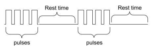
I'm new to msp430 registers and many things to learn. Your help will very much be appreciated.

#include <msp430g2553.h>
#define TIMER_OUT BIT2
int main(void)
{
WDTCTL = WDTPW + WDTHOLD; // Stop WDT
  if (CALBC1_1MHZ==0xFF)        // If calibration constant erased
  {                                        
    while(1);                               // do not load, trap CPU!! 
  }
  DCOCTL = 0;                               // Select lowest DCOx and MODx settings
  BCSCTL1 = CALBC1_1MHZ;                    // Set range
  DCOCTL = CALDCO_1MHZ;                     // Set DCO step + modulation */
  P1DIR |= TIMER_OUT;
  P1SEL |= TIMER_OUT;
  TACCR0 = 50-1; // PWM Period 50us (substract 1 because it's 0-based)
  TACCTL1 = OUTMOD_3;
  TACCR1 = 20; // CCR1 PWM duty cycle
  TACTL = TASSEL_2 + MC_1; // SMCLK, up mode
  _BIS_SR(CPUOFF); // Enter LPM0
}
  • Hi Kim,
    You could try using another timer to modulate the first timer. Unless, do you just need a single pulse? This could be doen with PWM generation.
  • Hi Cameron,
    I do not undestand your statement: You could try using another timer to modulate the first timer.
    What do you mean?
    How it can be done?
  • A simpler method might be to just count periods: Interrupt once per period (I suggest the CCR1 CCIE), and use that to increment a software counter. On period 4, change the OUTMOD to 0 (with OUT=0), to suppress the pulse generation. When the count gets to 1004-1, set the OUTMOD back to set/reset and set your software counter back to 0.

    This is analogous to what Cameron LaFollette was suggesting, but doesn't consume another timer.

  • Thanks for the response. I'll try those ideas however I'm confused using MSP430s registers and having a hard time to implement. Maybe you could provide some code snippets.

  • I suppose if llmars can do this, so can I. I think there's a similar discussion going on elsewhere, so maybe this will help them as well.

    ///
    //  main.c
    //  This generates a burst-pulsed output. At frequency LONG_HZ, it sends
    //  out SHORT_CNT pulses each of length SHORT_PERIOD (usec).
    //
    #include <msp430.h>
    #include <stdint.h>
    
    //  Set-able (within some limits)
    //  These settings produce a visible output on an LED at P1.6.
    #define LONG_HZ      1UL           // Long cycle repeats at 1Hz
    #define SHORT_PERIOD 50000UL       // Short (PWM) period: 50000 timer ticks = 50ms, long enough to see
    #define SHORT_CNT    4U            // 4 Short pulses in each Long period
    
    //  Derived
    #define TIMER_HZ     1000000UL     // Timer ticks at 1MHz (SMCLK/8 [ID=3])
    #define LONG_PERIOD  (TIMER_HZ/LONG_HZ)     // Timer ticks in a Long period
    #define LONG_CNT     (LONG_PERIOD/SHORT_PERIOD) // PWM cycles in a Long period
    
    //  Count from 1 to LCNT, to keep track of Long period.
    uint16_t short_cycles;
    
    //  OUTMOD=7 provides non-inverted PWM (high, then low), which is what people expect.
    //  It is also low in the second half, so we can switch to OUT=0 without glitching.
    #define CCTL_OUTMOD (OUTMOD_7)
    #define CCTL_OUT    (0*OUT)
    
    ///
    //  pulse_isr()
    //  Interrupts every SHORT_PERIOD timer ticks, but the deadline is SHORT_PERIOD/2, so don't dawdle.
    //
    #pragma vector=TIMER0_A1_VECTOR
    __interrupt void
    pulse_isr(void)
    {
        TA0CCTL1 &= ~CCIFG;     //  We really should look at TA0IV, but we only enable CCTL1:CCIE
    
        ++short_cycles;         // Count up (Short) PWM cycles
    
        //  For the first SHORT_CNT PWM cycles, just let the PWM run
        if (short_cycles < SHORT_CNT)
        {
            /*EMPTY*/
        }
        //  For the next (LONG_CNT-SHORT_CNT) cycles, hold it low using OUT=0
        else if (short_cycles < LONG_CNT)
        {
            //  Force it low using OUTMOD=0, OUT=0
            //  We do this repeatedly, but that's cheaper than checking.
            TA0CCTL1 &= ~OUTMOD_7;      // OUTMOD=0 (OUT). We set OUT(=0) earlier.
        }
        //  After LONG_CNT short (PWM) cycles, restart the long cycle
        else
        {
            //  Restart PWM. The output won't change until the second half-cycle ends.
            TA0CCTL1 |= CCTL_OUTMOD;   // Back to reset/set
            short_cycles = 0;
        }
        return;
    }
    
    //
    // main()
    //
    int
    main(void)
    {
    	WDTCTL = WDTPW | WDTHOLD;	// stop watchdog timer
    	
    	//  The request was for 50us (short period) pulses, which is not long
    	//  enough to reliably get through the ISR at 1MHz.
    	//  The next higher calibrated speed is 8MHz, so we use that.
    	DCOCTL = CALDCO_8MHZ;
    	BCSCTL1 = CALBC1_8MHZ;
    
    	//  Timer: PWM (50% duty, period SHORT_PERIOD) on P1.6=TA0.1
        //  SMCLK=8MHz, so divide by /8 to get TIMER_HZ=1MHz
        short_cycles = 0;
    	P1SEL |= BIT6;              // P1SEL.6=1 sets P1.6=TA0.1 [Ref SLAS735J Table 19]
    	P1DIR |= BIT6;              // Set it to output since timer won't [Also Table 19]
    	TA0CCR0 = SHORT_PERIOD-1;   // Short cycle time (1MHz ticks)
    	TA0CCR1 = SHORT_PERIOD/2-1; // 50% duty, for no particular reason
    	TA0CCTL1 = CCTL_OUTMOD|CCTL_OUT|CCIE;   // OUTMOD_7, OUT=0, IE
    	TA0CTL = TASSEL_2 | ID_3 | MC_1 | TACLR; // SMCLK, /8, Up (,Clear)
    
    	_EINT();                    // Enable the ISR
    	while (1)
    	{
    	    LPM0;                   // Nothing much to do here
    	}
    	/*NOTREACHED*/
    	return 0;
    }
    

    [Disclaimer: No warranty. No support. I may not even exist.]

  • Wow. Thank you so much Bruce. I'll try it later if I have my oscilloscope.
  • First bug report: I'm pretty sure the first-ever pulse doesn't happen, i.e. the first burst has only 3 pulses. I'm also pretty sure this fixes it, but I don't have a scope here and it's hard to see on the LED:

    Replace:
    TA0CTL = TASSEL_2 | ID_3 | MC_1 | TACLR; // SMCLK, /8, Up (,Clear)
    with
    TA0R = SHORT_PERIOD-2; // Force EQU0 real soon, to get first pulse
    TA0CTL = TASSEL_2 | ID_3 | MC_1; // SMCLK, /8, Up (,No Clear)
  • The code works. I have just test it on my scope. Thanks Bruce.
  • Hi Bruce, can you convert this code into Energia sketch using Energia libraries (.ino file)? I'm building a GUI in Processing, it would be easier if I could integrate the code into Energia.

  • I don't know much about Energia. I suspect you'd just move the while(1) into loop(), and the rest of main into init(), but I can't help much beyond that.

**Attention** This is a public forum