Tool/software: TI-RTOS
Hi guy
I now need to verify standard SPI communication under the TI-RTOS framework use EXP_MSP430F5529LP development board , I can not find a reference under the relevant examples of TI-RTOS for MSP430, now I can only simulate the framework of IIC to do related operations, and find that I can not read the data, I really do not know where the problem! Does anyone provide guidance or reference? my related code is as follows, Thanks,
1. main.c
void SPI_Master_Write_Byte(uint8_t cmd, uint8_t *txBuf, uint8_t txBuf_Size)
{
    uint8_t i;
    uint8_t txBuffer[20];

    if(cmd == NULL || txBuf_Size <= 0 || txBuf_Size > 19)
        return;

    txBuffer[0] = cmd;
     for(i=1;i<txBuf_Size+1;i++)
         txBuffer[i] = txBuf[i-1];

    SPI_Transaction spiTransaction;
    spiTransaction.txBuf = txBuffer;
    spiTransaction.rxBuf = NULL;
    spiTransaction.count = txBuf_Size+1;

    //cs low
    GPIO_setOutputLowOnPin(GPIO_PORT_P2, GPIO_PIN0);

    if (SPI_transfer(spi_master, &spiTransaction) == NULL) {
        System_printf("SPI Bus fault\n");
        System_flush();
    }

    //cs hight
    GPIO_setOutputHighOnPin(GPIO_PORT_P2, GPIO_PIN0);

}

void SPI_Master_Read_Byte(uint8_t cmd, uint8_t *rxBuf,uint8_t rxBuf_Size)
{
    if(cmd == NULL || rxBuf_Size <= 0 || rxBuf_Size > 19)
        return;

    SPI_Transaction spiTransaction;
    spiTransaction.txBuf = NULL;
    spiTransaction.rxBuf = rxBuf;
    spiTransaction.count = rxBuf_Size+1;

    //cs low
    GPIO_setOutputLowOnPin(GPIO_PORT_P2, GPIO_PIN0);

    char txbuf[1];
    txbuf[0] = cmd;
    spiTransaction.txBuf = txbuf;
    spiTransaction.rxBuf = NULL;
    spiTransaction.count = 1;

    if (SPI_transfer(spi_master, &spiTransaction) == NULL) {
        System_printf("SPI Bus fault\n");
        System_flush();
    }

    spiTransaction.txBuf = NULL;
    spiTransaction.rxBuf = rxBuf;
    spiTransaction.count = rxBuf_Size;

    if (SPI_transfer(spi_master, &spiTransaction) == NULL) {
        System_printf("SPI Bus fault\n");
        System_flush();
    }

    //cs hight
    GPIO_setOutputHighOnPin(GPIO_PORT_P2, GPIO_PIN0);
}

/*
 *  ======== taskFxn ========
 *  Task for this function is created statically. See the project's .cfg file.
 */
Void spi_master_taskFxn(UArg arg0, UArg arg1)
{
    /* Create I2C for usage */
    SPI_Params_init(&spi_master_Params);
    spi_master_Params.transferMode  = SPI_MODE_CALLBACK;
    spi_master_Params.mode          = SPI_MASTER;
    spi_master_Params.bitRate       = 1000000,            /* bitRate Hz*/
    spi_master_Params.dataSize      = 8;
    spi_master_Params.frameFormat   = SPI_POL0_PHA0;
    spi_master = SPI_open(Board_SPI_MASTER, &spi_master_Params);
    if (spi_master == NULL) {
        System_abort("Error Initializing SPI\n");
    }
    else {
        System_printf("SPI Initialized!\n");
    }
    System_flush();

    while(1){
        Task_sleep(1000);
        memset(SlaveType2,0,TYPE_2_LENGTH);
        SPI_Master_Read_Byte(CMD_TYPE_2_SLAVE,SlaveType2,TYPE_2_LENGTH);;
        printf("%s\r\n",SlaveType2);

        GPIO_toggle(Board_LED_P4_7);;
    }

    /* Deinitialized SPI */
    //SPI_close(spi_master);
    //System_printf("SPI closed!\n");
    //System_flush();
}

/*
 *  ======== main ========
 */
int main(void)
{
    /* Call board init functions */
    Board_initGeneral();
    Board_initGPIO();
    Board_initSPI();

    //Construct heartBeat Task  thread
    Task_Params taskParams;
    Task_Params_init(&taskParams);

    //i2c master
    taskParams.arg0         = 1000;
    taskParams.stackSize    = TASKSTACKSIZE;
    taskParams.stack        = &spi_master_taskStack;
    Task_construct(&spi_master_taskStruct, (Task_FuncPtr)spi_master_taskFxn, &taskParams, NULL);

    /* Start BIOS */
    BIOS_start();

    return (0);
}
2. MSP_EXP430F5529LP.c
/*
* =============================== DMA ===============================
*/
/*
* ======== MSP_EXP430F5529LP_isrDMA ========
* This is a application defined DMA ISR. This ISR must map and call the
* appropriate Driver_event(handle) API to indicate completed DMA transfers.
*/
Void MSP_EXP430F5529LP_isrDMA(UArg arg)
{
/* Call the SPI DMA function, passing the SPI handle used for WiFi */
SPI_serviceISR((SPI_Handle) &(SPI_config[0]));
}
/*
* =============================== SPI ===============================
*/
/* Place into subsections to allow the TI linker to remove items properly */
#if defined(__TI_COMPILER_VERSION__)
#pragma DATA_SECTION(SPI_config, ".const:SPI_config")
#pragma DATA_SECTION(spiUSCIADMAHWAttrs, ".const:spiUSCIADMAHWAttrs")
#endif
#include <ti/drivers/SPI.h>
#include <ti/drivers/spi/SPIUSCIADMA.h>
SPIUSCIADMA_Object spiUSCIADMAObjects[MSP_EXP430F5529LP_SPICOUNT];
uint8_t spiUSCIADMAscratchBuf[MSP_EXP430F5529LP_SPICOUNT];
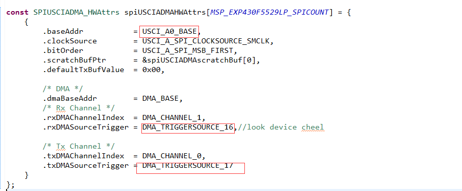
const SPIUSCIADMA_HWAttrs spiUSCIADMAHWAttrs[MSP_EXP430F5529LP_SPICOUNT] = {
{
.baseAddr = USCI_A0_BASE,
.clockSource = USCI_A_SPI_CLOCKSOURCE_SMCLK,
.bitOrder = USCI_A_SPI_MSB_FIRST,
.scratchBufPtr = &spiUSCIADMAscratchBuf[0],
.defaultTxBufValue = 0,
/* DMA */
.dmaBaseAddr = DMA_BASE,
/* Rx Channel */
.rxDMAChannelIndex = DMA_CHANNEL_1,
.rxDMASourceTrigger = DMA_TRIGGERSOURCE_18,
/* Tx Channel */
.txDMAChannelIndex = DMA_CHANNEL_0,
.txDMASourceTrigger = DMA_TRIGGERSOURCE_19
}
};
const SPI_Config SPI_config[] = {
{
.fxnTablePtr = &SPIUSCIADMA_fxnTable,
.object = &spiUSCIADMAObjects[0],
.hwAttrs = &spiUSCIADMAHWAttrs[0]
},
{NULL, NULL, NULL},
};
/*
* ======== MSP_EXP430F5529LP_initSPI ========
*/
// MSP430F5529
// -----------------
// /|\ | P2.0|-> Slave Chip Select (GPIO)
// | | |
// | P3.3|-> Data Out (UCA0SIMO)
// | |
// Button ->|P1.1 P3.4|<- Data In (UCA0SOMI)
// | |
// | P2.7|-> Serial Clock Out (UCA0CLK)
void MSP_EXP430F5529LP_initSPI(void)
{
/*
* NOTE: TI-RTOS examples configure USCIB0 as either SPI or I2C. Thus,
* a conflict occurs when the I2C & SPI drivers are used simultaneously in
* an application. Modify the pin mux settings in this file and resolve the
* conflict before running your the application.
*/
/* Configure CS pins to disable spi slave device*/
GPIO_setAsOutputPin(GPIO_PORT_P2, GPIO_PIN0);
GPIO_setOutputHighOnPin(GPIO_PORT_P2, GPIO_PIN0);
/* Configure Slave Reset Contrl pins to disable spi slave device*/
//GPIO_setAsOutputPin(GPIO_PORT_P1, GPIO_PIN5);
//GPIO_setOutputHighOnPin(GPIO_PORT_P1, GPIO_PIN5);
//GPIO_setOutputLowOnPin(GPIO_PORT_P1, GPIO_PIN5); // Now with SPI signals initialized,
//__delay_cycles(100000);
//GPIO_setOutputHighOnPin(GPIO_PORT_P1, GPIO_PIN5); // reset slave
//__delay_cycles(100000); // Wait for slave to initialize
/* SPI CLK */
GPIO_setAsPeripheralModuleFunctionOutputPin(GPIO_PORT_P2, GPIO_PIN7);
/* MOSI/SIMO */
GPIO_setAsPeripheralModuleFunctionOutputPin(GPIO_PORT_P3, GPIO_PIN3);
/* MISO/SOMI */
GPIO_setAsPeripheralModuleFunctionInputPin(GPIO_PORT_P3, GPIO_PIN4);
SPI_init();
}
3. .cfg
/* ================ Hwi configuration ================ */
var halHwi = xdc.useModule('ti.sysbios.hal.Hwi');
var msp430Hwi = xdc.useModule('ti.sysbios.family.msp430.Hwi');
halHwi.checkStackFlag = true;
//halHwi.checkStackFlag = false;


var hwiParams = new halHwi.Params();

/* DMA Hwi for the SPIUSCI driver */
//SPIUSCIBDMA_hwiIntFxn
//DMA_VECTOR      50
//USCI_B0_VECTOR  55
//USCI_A0_VECTOR  56
hwiParams.arg = 0;
halHwi.create(50, "&MSP_EXP430F5529LP_isrDMA", hwiParams);