This thread has been locked.
If you have a related question, please click the "Ask a related question" button in the top right corner. The newly created question will be automatically linked to this question.
Tool/software: TI-RTOS
Hi ,
Can anyone suggest me the hardware connections and the sample program for uart data transfer using msp432e401y launchpad. I want to transmit the data to the external sensor using uart.
I have attached the block diagram that i have used and i am using uartecho program. and i have few more
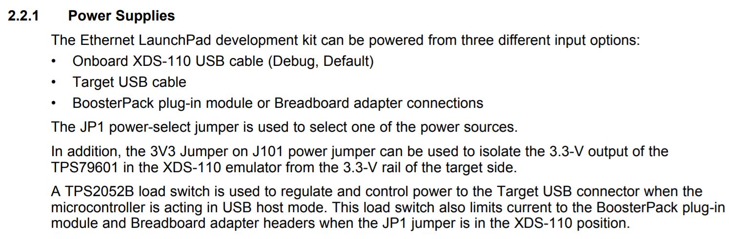
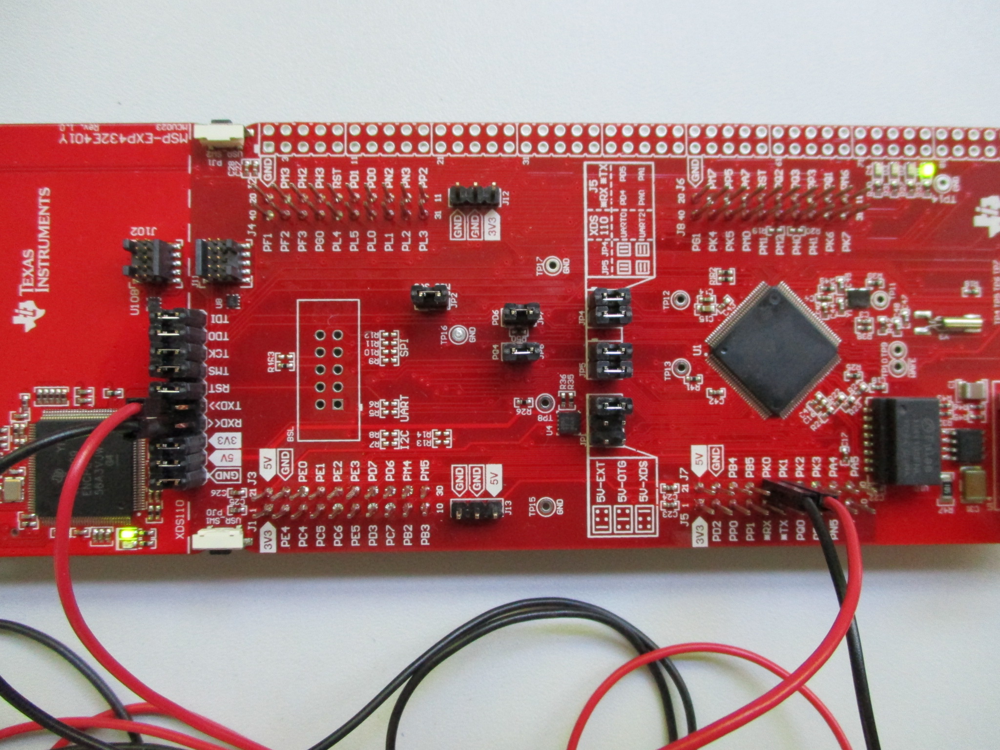
1. can i power on the kit using the mini usb near by RJ45 connector in the launchpad.
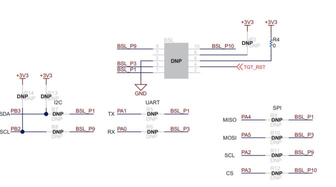
2. To configure it ifor uart data transfer am i need to use the R5 & R6 resistors as shown in the figure or these are for serial boot loading.
Thank you
Regards
Kalyan K.
Hi chris,
Thanks for the reply.However i have not got the answer for the question whether the hardware connections are write or not?.
actually, i have removed jumpers on JP4 & JP5 connectors and connected PA0 pin in JP4 to max3232 pin 14(TX) and PA1 pin in JP5 to pin 13(Rx). and i have flashed uartecho program.
will this work sir?
or
If i use UART4 Pins in J7 header, PK0 & PK1 instead of PA0 & PA1, what must be the changes in uartecho program.
Thank you
Regards
kalyan.
Hi,
I have made these changes in the uartecho program for transferring data with uart4 port , however it is not happening.
Can anyone help me
Hi Kalyan,
this code doubling is not as it works with the TI Drivers. It is intended to extend the given arrays.
MSP_EXP432E401Y_UART4 is an index into those arrays, thus it should be 1 and not 4 (after extending UART_config).
As a first step I would simply use the existing code and map it to a different uart. This is done in the uartMSP432E4HWAttrs array.
It should look like:
const UARTMSP432E4_HWAttrs uartMSP432E4HWAttrs[MSP_EXP432E401Y_UARTCOUNT] = {
{
.baseAddr = UART4_BASE,
.intNum = INT_UART4,
.intPriority = (~0),
.flowControl = UARTMSP432E4_FLOWCTRL_NONE,
.ringBufPtr = uartMSP432E4RingBuffer[MSP_EXP432E401Y_UART0],
.ringBufSize = sizeof(uartMSP432E4RingBuffer[MSP_EXP432E401Y_UART0]),
.rxPin = UARTMSP432E4_PK0_U4RX,
.txPin = UARTMSP432E4_PK1_U4TX,
.ctsPin = UARTMSP432E4_PIN_UNASSIGNED,
.rtsPin = UARTMSP432E4_PIN_UNASSIGNED,
.errorFxn = NULL
}
};
For clarity you could rename "MSP_EXP432E401Y_UART0" to "MSP_EXP432E401Y_UART4", but keep its value 0 for this redirection approach.
It you are interested in using multiple uarts you have to change the value "MSP_EXP432E401Y_UARTCOUNT" to the number of uarts you are going to use. Additionally you have to extend the arrays.
Example:
#define MSP_EXP432E401Y_UARTCOUNT 2
...
const UARTMSP432E4_HWAttrs uartMSP432E4HWAttrs[MSP_EXP432E401Y_UARTCOUNT] = {
{
.baseAddr = UART0_BASE,
.intNum = INT_UART0,
.intPriority = (~0),
.flowControl = UARTMSP432E4_FLOWCTRL_NONE,
.ringBufPtr = uartMSP432E4RingBuffer[MSP_EXP432E401Y_UART0],
.ringBufSize = sizeof(uartMSP432E4RingBuffer[MSP_EXP432E401Y_UART0]),
.rxPin = UARTMSP432E4_PA0_U0RX,
.txPin = UARTMSP432E4_PA1_U0TX,
.ctsPin = UARTMSP432E4_PIN_UNASSIGNED,
.rtsPin = UARTMSP432E4_PIN_UNASSIGNED,
.errorFxn = NULL
},
{
.baseAddr = UART4_BASE,
.intNum = INT_UART4,
.intPriority = (~0),
.flowControl = UARTMSP432E4_FLOWCTRL_NONE,
.ringBufPtr = uartMSP432E4RingBuffer[MSP_EXP432E401Y_UART4],
.ringBufSize = sizeof(uartMSP432E4RingBuffer[MSP_EXP432E401Y_UART4]),
.rxPin = UARTMSP432E4_PK0_U4RX,
.txPin = UARTMSP432E4_PK1_U4TX,
.ctsPin = UARTMSP432E4_PIN_UNASSIGNED,
.rtsPin = UARTMSP432E4_PIN_UNASSIGNED,
.errorFxn = NULL
}
};
const UART_Config UART_config[MSP_EXP432E401Y_UARTCOUNT] = {
{
.fxnTablePtr = &UARTMSP432E4_fxnTable,
.object = &uartMSP432E4Objects[MSP_EXP432E401Y_UART0],
.hwAttrs = &uartMSP432E4HWAttrs[MSP_EXP432E401Y_UART0]
},
{
.fxnTablePtr = &UARTMSP432E4_fxnTable,
.object = &uartMSP432E4Objects[MSP_EXP432E401Y_UART4],
.hwAttrs = &uartMSP432E4HWAttrs[MSP_EXP432E401Y_UART4]
}
};
I didn't check this example, thus please don't blame me for typos.
Hi Sven Probst,
Thank you for the reply.
I have changed the code as per your suggestion however i'm not able to transfer the data through the uart.
could you please let me know whether the hardware connections are right or not. The hardware connections are as given below:
1. J7 header, PK0 & PK1 to max3232 RX & TX.
2. I have not changed jumper settings. I have placed as it is in default condition(as per the datasheet).
3.through xds usb i am flashing the code.
4.I have placed JP1 jumper to XDS.
Regards,
Kalyan.
Hi Kalyan,
I just tried the following modification of the uartecho example and it worked:
/* UART configuration structure */
const UARTMSP432E4_HWAttrs uartMSP432E4HWAttrs[MSP_EXP432E401Y_UARTCOUNT] = {
{
//.baseAddr = UART0_BASE,
.baseAddr = UART4_BASE,
//.intNum = INT_UART0,
.intNum = INT_UART4,
.intPriority = (~0),
.flowControl = UARTMSP432E4_FLOWCTRL_NONE,
.ringBufPtr = uartMSP432E4RingBuffer[MSP_EXP432E401Y_UART0],
.ringBufSize = sizeof(uartMSP432E4RingBuffer[MSP_EXP432E401Y_UART0]),
//.rxPin = UARTMSP432E4_PA0_U0RX,
.rxPin = UARTMSP432E4_PK0_U4RX,
//.txPin = UARTMSP432E4_PA1_U0TX,
.txPin = UARTMSP432E4_PK1_U4TX,
.ctsPin = UARTMSP432E4_PIN_UNASSIGNED,
.rtsPin = UARTMSP432E4_PIN_UNASSIGNED,
.errorFxn = NULL
}
};
const UART_Config UART_config[MSP_EXP432E401Y_UARTCOUNT] = {
{
.fxnTablePtr = &UARTMSP432E4_fxnTable,
.object = &uartMSP432E4Objects[MSP_EXP432E401Y_UART0],
.hwAttrs = &uartMSP432E4HWAttrs[MSP_EXP432E401Y_UART0]
}
};
PK0 is the receive input of the processor. It has to be connected to the ROUT output of max3232.
PK1 is the transmit output of the processor. It has to be connected to the DIN input of max3232.
You could also use the virtual com port of the XDS110. See image:
Hi Kalyan,
one more thing just to be sure: max3232 ground and the MSP-EXP432E401Y ground must be connected. max3232 ground and D-Sub connector ground must be connected, too.
**Attention** This is a public forum