This thread has been locked.

If you have a related question, please click the "Ask a related question" button in the top right corner. The newly created question will be automatically linked to this question.

MSP430G2553: I2C master transmit code, both SCL and SDA pulled up and stay in this state.

Part Number: MSP430G2553

I am struggling with the I2C interface programming with MSP430G2553 MCU. I did not plug the slave device to test it, but I expected to have at least the slave address to be send over the I2C. I use internal resistors pull ups and ACLK to clock USCI. Here is my code:

#include <msp430.h>

int main(void) {
  WDTCTL = WDTPW + WDTHOLD;                 // Stop watchdog timer
  DCOCTL  = CALDCO_1MHZ;
  BCSCTL1 = CALBC1_1MHZ;

  // ACLK setup: VLO/8
  BCSCTL1 &= ~XTS;                          // Select Low-Frequency clock
  BCSCTL3 = (BCSCTL3 & ~LFXT1S_3) | LFXT1S_2; // Select VLO
  BCSCTL1 = (BCSCTL1 & ~DIVA_3) | DIVA_3;   // VLO/8 divider

  UCB0CTL1 |= UCSWRST;
  UCB0CTL0 = UCMST + UCMODE_3 + UCSYNC;
  UCB0CTL1 |=  UCSSEL1; // Use ACLK
  UCB0BR0 = 180;
  UCB0BR1 = 0;
  UCB0I2CSA = 0x52;
  P1SEL  |= BIT7 + BIT6;
  P1SEL2 |= BIT7 + BIT6;
  P1REN |= BIT6 + BIT7;
  P1OUT |= BIT6 + BIT7;
  UCB0CTL1 &= ~UCSWRST;
  __delay_cycles(200);
  while (UCB0STAT & UCBBUSY);

  UCB0CTL1 |= UCTR + UCTXSTT;
  while (UCB0CTL1 & UCTXSTT);
  UCB0TXBUF = 0x36;
  while (!(UCB0TXIFG & UCB0TXIFG));
  while (UCB0STAT & UCBBUSY);
  UCB0CTL1 |= UCTXSTP;
  while (UCB0CTL1 & UCTXSTP);
  while(1);
}

When debugging I see that the code gets stuck at the following line:

while (UCB0CTL1 & UCTXSTT);

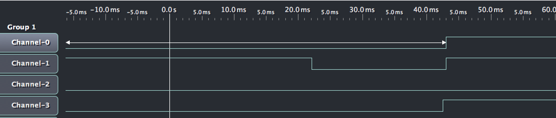
The logic sniffer with the BusPirate device, shows that after initialization, both SDA and SCL are pulled high and stay in this state.

Here the Channel-0 is P1.6 (SCL); Channel-1 is P1.7 (SDA) and Channel-3 is PIN16 (RST). I use MSP-EXP430G2 Rev 1.5 launchpad for the test.

  • Hi Nikita,

    you write you are using the internal pull-up resistors, they are typ. 35kOhm. Recommended is a value between 1-10kOhm, typ. 4.7kOhm.
    Another thing I noticed is the missing START sequence in your screenshot. The START sequence is defined as SCL=HIGH AND SDA=Falling Edge.

    Please have a look into this application note: "Solutions to Common eUSCI and USCI Serial Communication Issues on MSP430TM MCUs" http://www.ti.com/lit/slaa734

    Also have a look into the code examples for the I2C module of the MSP430G2553: dev.ti.com/.../

    Best regards,
    Andre
  • > Another thing I noticed is the missing START sequence in your screenshot.

    Could you please point me to the error in my code? I set the UCTXSTT flag, but the START sequence is not being executed. That what confuses me.
    What was done wrong?
  • Hi,

    having a look at the scope plot, another thing is strange. As long as RST (Ch3) is low, the MSP is kept in RESET state, that means there should not be any toggling on the port pins, but at around 22ms Ch1 is going low. I assume you are using a digital scope, thus Ch3 could be floating during that time.

    To better debug...
    ... can you please attach external pull up resistors to P1.6 and P1.7 and disable lines #20 and #21 (removing internal pull-ups)?
    ... can you set a Port Pin to high as trigger point for debugging? E.g. configure P1.0 as output driving low and set it to high in line #26?

    Then please run the program and capture a scope plot.

    Best regards,
    Andre
  • Hi,

    do you have further questions? If not, please select "Resolved" for the post that solved your issue so this thread can be closed out.
    Thanks a lot!

    Best regards,
    Andre
  • Hi,

    I suppose that you were able to move on with your application as you didn't reply anymore, so I'll close this post.
    Please feel free to comment again if you look for further assistance, it will re-open the thread.

    Best regards,
    Andre

**Attention** This is a public forum