This thread has been locked.
If you have a related question, please click the "Ask a related question" button in the top right corner. The newly created question will be automatically linked to this question.
Hi There,
I am working with MSP430FR2433 using msp430ware Version 3.80.14.01, curious about how I2C works,
so checked in Oscilloscope for pin P1.3, P1.2 in debug mode by resuming, both are not seen in oscilloscope.
as shown in below image:
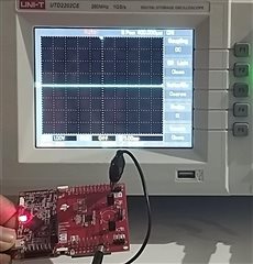
I was wondering why clock and data signals are not generated.
This is carried out when slave is not connected,
When suspended in debug mode, it was running following instruction of "eusci_b_i2c.c" file
//Poll for transmit interrupt flag. while (!(HWREG16(baseAddress + OFS_UCBxIFG) & UCTXIFG)) ;
The example (eusci_b_i2c_ex3_masterTxMultiple) code which i have used in this as follows:
// Demo - EUSCI_B0 I2C Master TX multiple bytes to MSP430 Slave #define SLAVE_ADDRESS 0x48 //***************************************************************************** // //Target frequency for SMCLK in kHz // //***************************************************************************** #define CS_SMCLK_DESIRED_FREQUENCY_IN_KHZ 1000 //***************************************************************************** // //SMCLK/FLLRef Ratio // //***************************************************************************** #define CS_SMCLK_FLLREF_RATIO 30 // Pointer to TX data uint8_t TXData = 0; uint8_t TXByteCtr; void main(void) { WDT_A_hold(WDT_A_BASE); //Set DCO FLL reference = REFO CS_initClockSignal( CS_FLLREF, CS_REFOCLK_SELECT, CS_CLOCK_DIVIDER_1 ); //Set Ratio and Desired MCLK Frequency and initialize DCO CS_initFLLSettle( CS_SMCLK_DESIRED_FREQUENCY_IN_KHZ, CS_SMCLK_FLLREF_RATIO ); //Set ACLK = VLO with frequency divider of 1 CS_initClockSignal( CS_ACLK, CS_VLOCLK_SELECT, CS_CLOCK_DIVIDER_1 ); //Set SMCLK = DCO with frequency divider of 1 CS_initClockSignal( CS_SMCLK, CS_DCOCLKDIV_SELECT, CS_CLOCK_DIVIDER_1 ); //Set MCLK = DCO with frequency divider of 1 CS_initClockSignal( CS_MCLK, CS_DCOCLKDIV_SELECT, CS_CLOCK_DIVIDER_1 ); // Configure Pins for I2C GPIO_setAsPeripheralModuleFunctionInputPin( GPIO_PORT_UCB0SCL, GPIO_PIN_UCB0SCL, GPIO_FUNCTION_UCB0SCL ); GPIO_setAsPeripheralModuleFunctionInputPin( GPIO_PORT_UCB0SDA, GPIO_PIN_UCB0SDA, GPIO_FUNCTION_UCB0SDA ); /* * Disable the GPIO power-on default high-impedance mode to activate * previously configured port settings */ PMM_unlockLPM5(); EUSCI_B_I2C_initMasterParam param = {0}; param.selectClockSource = EUSCI_B_I2C_CLOCKSOURCE_SMCLK; param.i2cClk = CS_getSMCLK(); param.dataRate = EUSCI_B_I2C_SET_DATA_RATE_400KBPS; param.byteCounterThreshold = 0; param.autoSTOPGeneration = EUSCI_B_I2C_NO_AUTO_STOP; EUSCI_B_I2C_initMaster(EUSCI_B0_BASE, ¶m); //Specify slave address EUSCI_B_I2C_setSlaveAddress(EUSCI_B0_BASE, SLAVE_ADDRESS ); //Set Master in receive mode EUSCI_B_I2C_setMode(EUSCI_B0_BASE, EUSCI_B_I2C_TRANSMIT_MODE ); //Enable I2C Module to start operations EUSCI_B_I2C_enable(EUSCI_B0_BASE); EUSCI_B_I2C_clearInterrupt(EUSCI_B0_BASE, EUSCI_B_I2C_TRANSMIT_INTERRUPT0 + EUSCI_B_I2C_NAK_INTERRUPT ); //Enable master Receive interrupt EUSCI_B_I2C_enableInterrupt(EUSCI_B0_BASE, EUSCI_B_I2C_TRANSMIT_INTERRUPT0 + EUSCI_B_I2C_NAK_INTERRUPT ); while(1) { __delay_cycles(1000); // Delay between transmissions TXByteCtr = 4; // Load TX byte counter TXData = 0; while (EUSCI_B_I2C_SENDING_STOP == EUSCI_B_I2C_masterIsStopSent(EUSCI_B0_BASE)); EUSCI_B_I2C_masterSendMultiByteStart(EUSCI_B0_BASE, TXData++); __bis_SR_register(CPUOFF + GIE); // Enter LPM0 w/ interrupts // Remain in LPM0 until all data // is TX'd // Increment data byte } } //------------------------------------------------------------------------------ // The USCIAB0TX_ISR is structured such that it can be used to transmit any // number of bytes by pre-loading TXByteCtr with the byte count. Also, TXData // points to the next byte to transmit. //------------------------------------------------------------------------------ #if defined(__TI_COMPILER_VERSION__) || defined(__IAR_SYSTEMS_ICC__) #pragma vector=USCI_B0_VECTOR __interrupt #elif defined(__GNUC__) __attribute__((interrupt(USCI_B0_VECTOR))) #endif void USCIB0_ISR(void) { switch(__even_in_range(UCB0IV, USCI_I2C_UCBIT9IFG)) { case USCI_NONE: // No interrupts break; break; case USCI_I2C_UCALIFG: // Arbitration lost break; case USCI_I2C_UCNACKIFG: // NAK received (master only) //resend start if NACK EUSCI_B_I2C_masterSendStart(EUSCI_B0_BASE); break; case USCI_I2C_UCTXIFG0: // TXIFG0 // Check TX byte counter if (TXByteCtr) { EUSCI_B_I2C_masterSendMultiByteNext(EUSCI_B0_BASE, TXData++); // Decrement TX byte counter TXByteCtr--; } else { EUSCI_B_I2C_masterSendMultiByteStop(EUSCI_B0_BASE); // Exit LPM0 __bic_SR_register_on_exit(CPUOFF); } break; default: break; } }
After this checked with MasterTxSingle example there also SCL(clock) is not generated.
Looking for insights for the above.
Thanks and regards,
Ajaykumar V
I don't see any pullup resistors on P1.2/.3. The Launchpad doesn't supply these. Many/most commercial I2C-slave boards do supply them (which is handy). For this experiment, you could use the internal pullups by adding (before the calls to GPIO_setAsPeripheralModuleFunctionInputPin) something like:
> GPIO_setAsInputPinWithPullUpResistor(GPIO_PORT_UCB0SCL, (GPIO_PIN_UCB0SCL|GPIO_PIN_UCB0SDA)); // We "know" they're both on P1
---------
Unsolicited: It looks like your scope is on Auto, so you might miss the SCL even if it appears. Try triggering on the SCL Falling edge (maybe even "Single-Shot" if you have it).
**Attention** This is a public forum